Kia Optima Hybrid: Panoramaroof / Panoramaroof Motor Repair procedures
| Inspection |
| 1. |
Disconnect the negative (-) battery terminal. |
| 2. |
Remove the roof trim.
(Refer to the BD group - "Roof trim") |
| 3. |
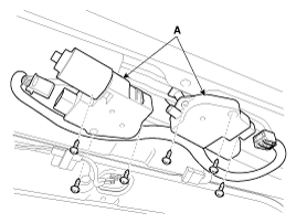
Disconnect the panoramaroof motor (A) connector.
|
| 4. |
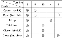
Ground the terminals as below table, and check that the panoramaroof unit operates.
|
| 5. |
Make these input tests at the connector. If any test
indicates a problem, find and correct the cause, then recheck the
system. If all the input tests prove OK, the panoramaroof motor must be
faulty; replace it.
|
| 6. |
Ground the terminals as below table, and check that the roller blind motor operates.
|
| Resetting The Panoramaroof |
| 1. |
Turn the ignition key to the ON position and then close the panoramaroof completely. |
| 2. |
Release the panoramaroof control lever. |
| 3. |
Press and hold the CLOSE button for more than 10 seconds until the panoramaroof has moved slightly. |
| 4. |
Release the panoramaroof control lever. |
| 5. |
Press and hold the CLOSE button once again within 3 seconds until the panoramaroof do as follows;
|
| 6. |
Reset procedure of panorama system is finished. |
| 1. |
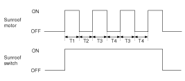
The panoramaroof ECU detects the Run- time of motor |
| 2. |
Motor can be operated continuously for the 1st run-time(120 ± 10sec.). |
| 3. |
The continuous operation of motor stops after the 1st Run-time(120 ± 10sec.). |
| 4. |
Then Motor is not operated for the 1st Cool-time(18 ± 2sec.). |
| 5. |
Motor is operated for the 2nd Run-time(10 ± 2sec.) at the continued motor operation after 1st Cool-time(18 ± 2sec.) |
| 6. |
The continuous operation of motor stops operating after the 2nd Run-time(10 ± 2sec.) |
| 7. |
Motor is not operated for the 2nd Cool-time(18 ± 2sec.). |
| 8. |
Motor repeats the 2nd run-time and 2nd cool-time at the continued motor operation.
T1 : 120 ± 10 sec., T2 : 18 ± 2 sec.,
T3 : 10 ± 2 sec., T4 : 18 ± 2 sec. |
 Panoramaroof Switch Repair procedures
Inspection 1. Disconnect the negative (-) battery terminal. 2. Remove the overhead console lamp assembly. (Refer to the BD group - "Roof trim") 3. Check for continuity between the terminals. 4. If the ...
 Lighting System
...
Other information:
Kia Optima Hybrid (TF HEV) 2016-2020 Service Manual: General Safety Information and Caution
Safety Precaution Since hybrid vehicles contain a high voltage battery, if the high voltage system or vehicles are handled incorrectly, this might lead to a serious accidents like electric shock and electric leakage. • Be sure to shut off the high voltage by removing the ...
Kia Optima Hybrid (TF HEV) 2016-2020 Service Manual: Steering Angle Sensor Description and Operation
Description The Steering Angle Sensor (SAS) is installed in MDPS (Motor Driven Power Steering) and it sends messages to HECU through CAN communication line. The SAS is used to determine turning direction and speed of the steering wheel. The HECU uses the signals from the SAS when performing ESC-related ...


