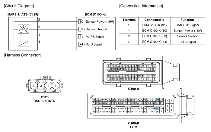
Kia Optima Hybrid: Engine Control System / Intake Air Temperature Sensor (IATS) Schematic Diagrams
| Circuit Diagram |

 Intake Air Temperature Sensor (IATS) Specifications
Specification Temperature [°C(°F)]Resistance (k?)-40(-40)40.93 ~ 48.35-20(-4)13.89 ~ 16.030(32)5.38 ~ 6.0910(50)3.48 ~ 3.9020(68)2.31 ~ 2.5740(104)1.08 ~ 1.2150(122)1.56 ~ 1.7460(140)0.54 ~ 0.6280(176)0.29 ...
 Intake Air Temperature Sensor (IATS) Repair procedures
Inspection 1. Turn the ignition switch OFF. 2. Disconnect the IATS connector. 3. Measure resistance between the IATS terminals 3 and 4. 4. Check that the resistance is within the specification. Temperature ...
Other information:
Kia Optima Hybrid (TF HEV) 2016-2020 Service Manual: Electric A/C compressor Specifications
Specification ModelESC33i MotroBLDC MotorControl TypeCANCompression TypeScrollCapacity33cc/revOperating Voltage Range190~320VRated Voltage288VMount TypeEngine Mounting, 6 Point Mounting ...
Kia Optima Hybrid (TF HEV) 2016-2020 Service Manual: General Safety Information and Caution
Instructions When Handling Refrigerant 1. R-134a liquid refrigerant is highly volatile. A drop on the skin of your hand could result in localized frostbite. When handling the refrigerant, be sure to wear gloves. 2. It is standard practice to wear goggles or glasses to protect your eyes, and gloves to ...
