Kia Optima Hybrid: Indicators And Gauges / Instrument Cluster Schematic Diagrams
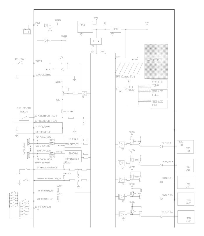
| Circuit Diagram |
 Instrument Cluster Description and Operation
Description Cluster Network Diagram ECMEngine Control ModuleHCUHybrid Control ModuleMCUMotor Control ModuleBMSBattery Management SystemTCMTransaxle Control ModuleEBSElectronic Brake SystemOPUOil ...
 Instrument Cluster Repair procedures
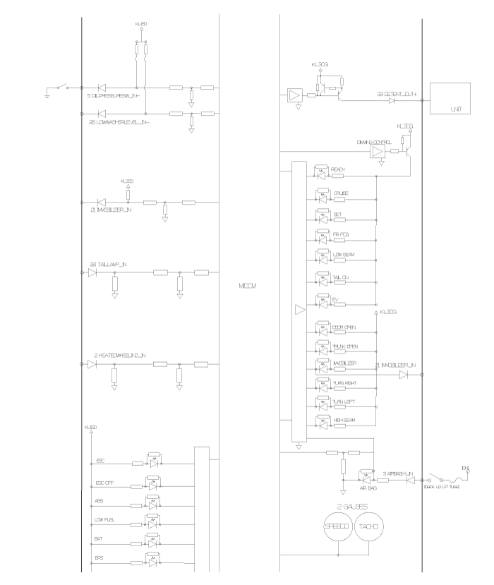
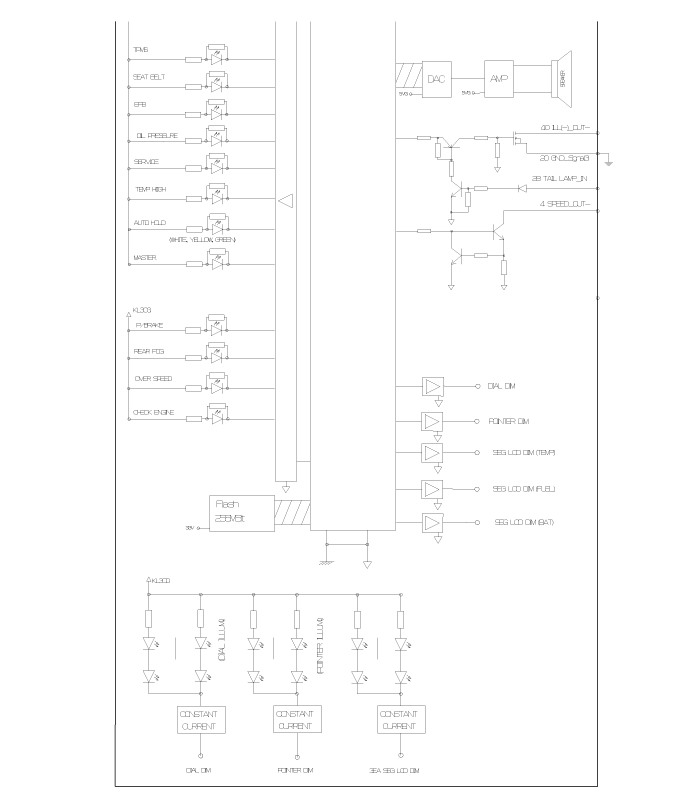
Inspection NORefSymbolNameSignal InputMessage NameSignal controlSignal Value(X: Don’t care)Illumination/Power1TurnLeftB-CANTurn LH Signal Lamp Switch Status for indicator in CLULED/B+2TurnRightB-CANTurn ...
Other information:
Kia Optima Hybrid (TF HEV) 2016-2020 Service Manual: Description and Operation
System Overview PAS(Parking Assist System) is an electronic driving aid device warning driver to be cautious when they park or speed low after detecting an object on side and behind of vehicle by using the feature of ultrasonic waves. PAS consists of four PS sensors which are detecting the obstacles ...
Kia Optima Hybrid (TF HEV) 2016-2020 Service Manual: Power Door Mirror Actuator Repair procedures
Inspection 1. Remove the front door quadrant delta cover. (Refer to the BD group - "Front door") 2. Disconnect the power door mirror connector from the harness. 3. Apply battery voltage to each terminal as shown in the table and verify that the mirror operates properly. Mirror Heater Inspection Turn ...