Kia Optima Hybrid: Automatic Transaxle Control System / Input Speed Sensor Repair procedures
| Inspection |
| 1. |
Check signal waveform of Input & output speed sensor using the GDS.
|
| Removal |
|
| 1. |
Remove the valve body assembly.
(Refer to Hydraulic System - "Valve Body") |
| 2. |
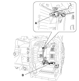
Disconnect the input & output speed sensor connector (A). |
| 3. |
Remove the input & output speed sensor (B) after removing the bolts.
|
| Installation |
| 1. |
Install in the reverse order of removal. |
|
 Input Speed Sensor Troubleshooting
Signal Waveform ...
 Output Speed Sensor Description and Operation
Description Input speed sensor is a vital unit that measures the rate of rotation of the input shaft inside the transaxle and delivers the readings to the TCM. The sensor provides critical input data that''s ...
Other information:
Kia Optima Hybrid (TF HEV) 2016-2020 Service Manual: Specifications
Specification ItemSpecificationUltrasonic sensorVoltage ratingDC 12 VDetecting range40 cm ~ 120 cmOperation voltageDC 9 ~ 12 VOperation currentMAX 300 mAOperation temperature-30°C ~ +80°C (-22°C ~ +176°C)Operation frequency48 ± 5 KHzNumber of sensorsFront : 4EA (Left side, Left center, Right center, ...
Kia Optima Hybrid (TF HEV) 2016-2020 Service Manual: Electric A/C compressor Specifications
Specification ModelESC33i MotroBLDC MotorControl TypeCANCompression TypeScrollCapacity33cc/revOperating Voltage Range190~320VRated Voltage288VMount TypeEngine Mounting, 6 Point Mounting ...


