Kia Optima Hybrid: Fuel Delivery System / Fuel Pump Repair procedures
| Removal |
| 1. |
Release the residual pressure in fuel line (Refer to “Release Residual Pressure in Fuel Line” in this group). |
| 2. |
Remove the fuel tank.
(Refer to "Fuel Tank" in this group) |
| 3. |
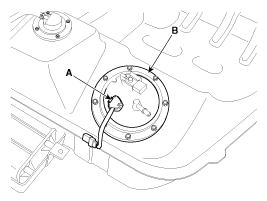
Disconnect the fuel tank pressure sensor & fuel pump connector (A). |
| 4. |
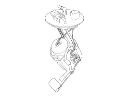
Remove the plate cover (B) after removing the installation bolt, and then remove the fuel pump from the fuel tank.
|
| Installation |
| 1. |
Install in the reverse order of removal.
|
 Fuel Line Repair procedures
Removal 1. Remove the fuel tank (Refer to “Fuel Tank”) 2. Disconnect the fuel feed tube (A). 3. Disconnect the vapor hose (A). 4. Disconnect the vapor hose quick-connector (A). 5. Remove the fuel tube ...
 Fuel Filter Repair procedures
Replacement 1. Remove the fuel pump (Refer to “Fuel Pump” in this group). 2. Disconnect the electric pump wiring connector (A) and the fuel sender connector (B). 3. Remove the cushion pipe fixing clip ...
Other information:
Kia Optima Hybrid (TF HEV) 2016-2020 Service Manual: Yaw-rate and Lateral G Sensor Repair procedures
Removal 1. Turn ignition switch OFF and disconnect the negative (-) battery cable. 2. Remove the floor console. (Refer to the Body group - "Console") 3. Disconnect the yaw rate & lateral G sensor connector (A). 4. Remove the mounting nuts (B). Tightening torque: 6.9 ~ 10.8 N.m (0.7 ~ 1.1 kgf.m, 5.1 ...
Kia Optima Hybrid (TF HEV) 2016-2020 Service Manual: Troubleshooting
Troubleshooting Trouble SymptomProbable causeRemedyVehicle pulls to one sideScoring of driveshaft ball jointReplaceWear, rattle or scoring of wheel bearingReplaceDefective front suspension and steeringAdjustment or ReplaceVibrationWear, damage or bending of driveshaftReplaceDriveshaft rattle and hub ...


