Kia Optima Hybrid: Engine Control System / Engine Control Module (ECM) Repair procedures
| Removal |
| 1. |
Shut off the High Voltage circuit.
(Refer to “High Voltage Shut-off Procedures”) |
| 2. |
Turn the ignition switch OFF and disconnect the auxiliary 12V negative (-) battery terminal. |
| 3. |
Remove the air cleaner assembly.
(Refer to Engine Mechanical System - "Intake And Exhaust System") |
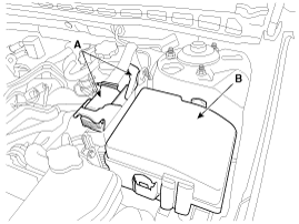
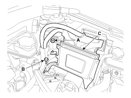
| 4. |
Disconnect the ECM connector (A) and remove the engine room relay box (B).
|
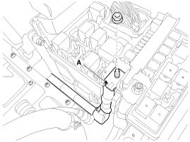
| 5. |
Disconnect the battery positive (+) terminal (A).
|
| 6. |
Remove the reservoir mounting bolt (A) and coolant outlet pipe mounting bolt (B).
|
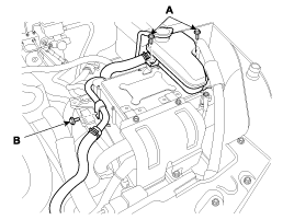
| 7. |
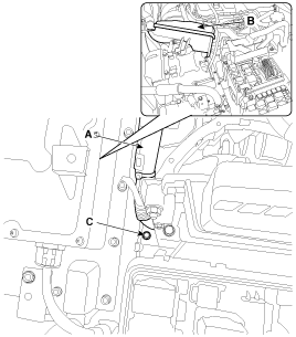
Make a gap for removing the ECM bracket mounting bolt (C) by
moving the battery cable (A) and the reservoir (B) as shown in the
illustration below and then remove the bolt (C).
|
| 8. |
Remove the ECM (C) by loosening the nut (A) and the bolt (B).
|
| Installation |
When replacing the ECM, the vehicle equipped with the smart key must be performed the procedure as below.
[In the case of installing used ECM]
[In the case of installing new ECM]
Turn the ignition ON and OFF position after completing "ECM neutral mode".
Then the ECM key register process is completed automatically.
|

ECM is combined with TCM. Therfore perform the necessary procedures after replacing or reinstalling a ECM.
(Refer to Automatic Transaxle Control System - "Adjustment")
|
| 1. |
Install in the reverse order of removal.
|
| ECM Problem Inspection Procedure |
| 1. |
TEST ECM GROUND CIRCUIT: Measure resistance between ECM and
chassis ground using the backside of ECM harness connector as ECM side
check point. If the problem is found, repair it.
|
| 2. |
TEST ECM CONNECTOR: Disconnect the ECM connector and visually
check the ground terminals on ECM side and harness side for bent pins
or poor contact pressure. If the problem is found, repair it. |
| 3. |
If problem is not found in Step 1 and 2, the ECM could be
faulty. If so, make sure there were no DTC''s before swapping the ECM
with a new one, and then check the vehicle again. If DTC''s were found,
examine this first before swapping ECM. |
| 4. |
RE-TEST THE ORIGINAL ECM: Install the original ECM (may be
broken) into a known-good vehicle and check the vehicle. If the problem
occurs again, replace the original ECM with a new one. If problem does
not occur, this is intermittent problem (Refer to “Intermittent
Problem Inspection Procedure” in Basic Inspection Procedure).
|
 Engine Control Module (ECM) Schematic Diagrams
ECM Terminal And Input/Output signal ECM Terminal Function Connector [C100-K] PinNo.DescriptionConnected to1Power groundChassis Ground2Battery power (B+)Ignition Switch3Power groundChassis Ground4Battery ...
 ETC (Electronic Throttle Control) System Description and Operation
Description The Electronic Throttle Control (ETC) System consists of a throttle body with an integrated control motor and throttle position sensor (TPS). Instead of the traditional throttle cable, an Accelerator ...
Other information:
Kia Optima Hybrid (TF HEV) 2016-2020 Service Manual: High Voltage Shut-off Procedures
High Voltage Shut-off Procedures Be sure to read and follow the “General Safety Information and Caution” before doing any work related with the high voltage system. Failure to follow the safety instructions may result in serious electrical injuries. • High voltage components: ...
Kia Optima Hybrid (TF HEV) 2016-2020 Service Manual: Interior Trim Repair procedures
Replacement Door Scuff Trim Replacement • Put on gloves to protect your hands. • Use a plastic panel removal tool to remove interior trim pieces to protect from marring the surface. • Take care not to bend or scratch the trim and panels. 1. Using a screwdriver or remover, remove the ...