Kia Optima Hybrid: Parking Brake System / Electric Parking Brake (EPB) Repair procedures
Kia Optima Hybrid (TF HEV) 2016-2020 Service Manual / Brake System / Parking Brake System / Electric Parking Brake (EPB) Repair procedures
| Removal |
EPB Unit
| 1. |
Turn ignition OFF and disconnect the negative (-) battery cable. |
| 2. |
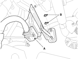
Disconnect the EPB control unit connecter (A).
|
| 3. |
Remove the EPB control unit mounting nuts (B) and the EPB control unit.
|
EPB Switch
| 1. |
Turn ignition OFF and disconnect the negative (-) battery cable. |
| 2. |
Remove the floor console upper cover.
(Refer to Body group - "Console") |
| 3. |
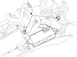
Remove the EPB switch assembly after loosening the screws (A).
|
| Installation |
EPB Unit
| 1. |
Installation is the reverse of removal. |
| 2. |
Check that the brake operates normally by pushing the EPB switch more than 3 times after installing the EPB module. |
EPB Switch
| 1. |
Install the EPB switch assembly to the floor console upper cover. |
| 2. |
After connecting the EPB switch connecter, install the floor console upper cover. (Refer to Body group - "Console") |
| 3. |
Connect the negative (-) battery cable. |
 Electric Parking Brake (EPB) Schematic Diagrams
EPB Circuit Diagram (1) EPB Circuit Diagram (2) EPB connector input/output Pin DescriptionPin Description1--21--2--22YC-CAN (Low)3--23WC-CAN (High)4--24WElectric Parking Brake Switch (SW1)5--25L/OElectric ...
Other information:
Kia Optima Hybrid (TF HEV) 2016-2020 Service Manual: Components and Components Location
Components Location 1. Drive shaft2. Lower arm3. Front disk4. Front strut assembly5. Steering gearbox6. Front stabilizer bar7. Sub frame ...
Kia Optima Hybrid (TF HEV) 2016-2020 Service Manual: Electric Parking Brake (EPB) Components and Components Location
Components 1. EPB Unit2. EPB Switch3. Brake Caliper 4. EPB Warning Lamp5. AUTO HOLD Lamp ...
© 2025 Copyright www.koptimatfhev.com


