Kia Optima Hybrid: Emission Control System / Components and Components Location
| Components Location |
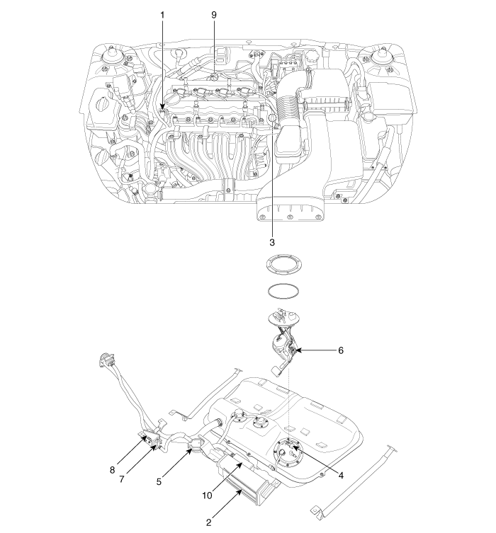
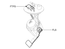
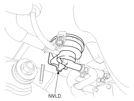
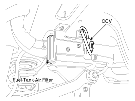
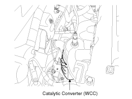
| 1. PCV valve 2. Canister 3. Purge control solenoid valve (PCSV) 4. Fuel tank pressure sensor (FTPS) 5. NVLD (Natural Vaccum Leakage Detection) Module | 6. Fuel level sender (FLS) 7. Canister Close Valve (CCV) 8. Fuel tank air filter 9. Catalytic converter 10. Auxiliary canister |
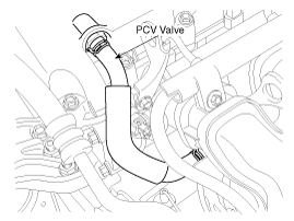
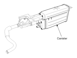
| 1. PCV Valve | 2. Canister |
|
|
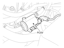
| 3. Purge Control Solenoid Valve (PCSV) | 4. Fuel Tank Pressure Sensor (FTPS) 6. Fuel Level Sender (FLS) |
|
|
| 5. NVLD (Natural Vaccum Leakage Detection) Module | 7. Canister Close Valve (CCV) 8. Fuel Tank Air Filter |
|
|
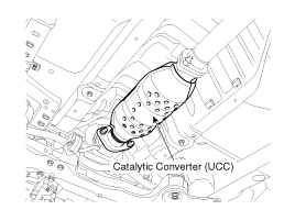
| 9. Catalytic Converter (WCC) | 9. Catalytic Converter (UCC) |
|
|
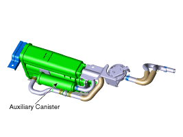
| 10. Auxiliary Canister | |
|
 Specifications
Specifications Purge Control Solenoid Valve (PCSV) ? Specification ItemSpecificationCoil Resistance (?)19.0 ~ 22.0 [20°C(68°F)] Fuel Tank Pressure Sensor (FTPS) ? Type: Piezo-Resistive Pressure Sensor ...
 Description and Operation
Description Emissions Control System consists of three major systems. • The Crankcase Emission Control System prevents blow-by gas from releasing into the atmosphere. This system recycles gas back into ...
Other information:
Kia Optima Hybrid (TF HEV) 2016-2020 Service Manual: Description and Operation
Description EPS (Electric power steering, Column assist type) system uses an electric motor to assist the steering force and it is an engine operation independent steering system. EPS control module controls the motor operation according to information received from the each sensor and CAN (Controller ...
Kia Optima Hybrid (TF HEV) 2016-2020 Service Manual: Active Air Flap(AAF) Schematic Diagrams
Schematic Diagram Circuit Diagram ...