Kia Optima Hybrid: Engine Control System / Canister Close Valve (CCV) Repair procedures
Kia Optima Hybrid (TF HEV) 2016-2020 Service Manual / Engine Control/Fuel System / Engine Control System / Canister Close Valve (CCV) Repair procedures
| Removal |
| 1. |
Turn the ignition switch OFF and disconnect the battery negative (-) terminal. |
| 2. |
Lift the vehicle. |
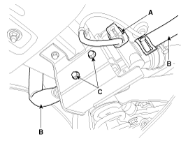
| 3. |
Disconnect the canister close valve connector (A). |
| 4. |
Disconnect the ventilation hose (B) from the fuel tank air filter and canister close valve. |
| 5. |
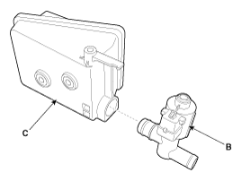
Remove the fuel tank air filter assembly after removing bolts (C).
|
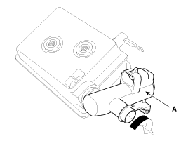
| 6. |
Release the lever (A), and then separate the canister close
valve (B) from the fuel tank air filter (C) after rotating it in the
direction of the arrow in the figure.
|
| Installation |
|

| 1. |
Install in the reverse order of removal. |
 Canister Close Valve (CCV) Schematic Diagrams
Circuit Diagram ...

Other information:
Kia Optima Hybrid (TF HEV) 2016-2020 Service Manual: Body Control Module (BCM) Components and Components Location
Components Connector Pin Information No.Connector A (24pin)Connector B (20pin)Connector C (24pin)1Battery (+)Head lamp low beam switchRoom lamp2IGN 1Head lamp high beam switchAV tail signal3IGN 2Front fog switchBuzzer (PAS)4ACCSafety power window EnableMirror unfolding relay5Mist switchK-LineRear left ...
Kia Optima Hybrid (TF HEV) 2016-2020 Service Manual: Rear Window Glass Repair procedures
Removal • Put on gloves to protect your hands. • Be careful not to damage the painted surface. 1. Remove the following items. • Roof moulding (Refer to the BD group- "Panoramaroof") • Rear seat (Refer to the BD group- "Rear Seat") • Rear pillar trim (Refer to the BD group- "Interior ...
© 2025 Copyright www.koptimatfhev.com