Kia Optima Hybrid: AHB(Active Hydraulic Boost) System / Brake Line Repair procedures
Kia Optima Hybrid (TF HEV) 2016-2020 Service Manual / Brake System / AHB(Active Hydraulic Boost) System / Brake Line Repair procedures
| Removal |
| 1. |
Disconnect the brake fiuid level switch connector, and remove the reservoir cap. |
| 2. |
Remove the brake fluid from the master cylinder reservior with a syringe.
|
| 3. |
Remove the wheel & tire. |
| 4. |
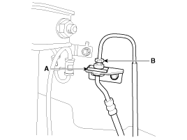
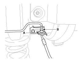
Remove the brake hose clip (A).
Front
Rear
|
| 5. |
Disconnect the brake tube by loosening the tube flare nut (B).
|
| 6. |
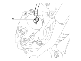
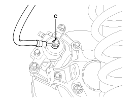
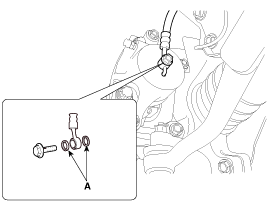
Disconnect the brake hose from the brake caliper by loosening the bolt (C).
Front
Rear
|
| Inspection |
| 1. |
Check the brake tubes for cracks, crimps and corrosion. |
| 2. |
Check the brake hoses for cracks, damage and fluid leakage. |
| 3. |
Check the brake tube flare nuts for damage and fluid leakage. |
| 4. |
Check brake hose mounting bracket for crack or deformation. |
| Installation |
| 1. |
Installation is the reverse of removal.
|
| 2. |
After installation, bleed the brake system.
(Refer to Brake system bleeding) |
| 3. |
Check the spilled brake oil. |
 Brake Line Components and Components Location
Components ...
 Brake Pedal Components and Components Location
Components 1. Brake pedal stroke sensor2. Stop lamp switch3. Brake pedal ...
Other information:
Kia Optima Hybrid (TF HEV) 2016-2020 Service Manual: Heater Unit Repair procedures
Replacement 1. Disconnect the negative (-) battery terminal. 2. Recover the refrigerant with a recovery/ recycling/ charging station. 1) Do not use the same A/C recovery / charging station as conventional belt-driven compressors. 2) Since the electric compressor uses high-voltage, you should ...
Kia Optima Hybrid (TF HEV) 2016-2020 Service Manual: Description and Operation
Description The Vehicle Information System is a Telematics service that ensures comfortable and enjoyable driving by providing safety, security, and vehicle diagnostic information, with the option of using your smartphone. The term "Telematics" is a combination of telecommunication and ...
© 2025 Copyright www.koptimatfhev.com


