Kia Optima Hybrid: Auto Head Lamp Leveling Device / Auto Head Lamp Leveling Unit Description and Operation
| Description |
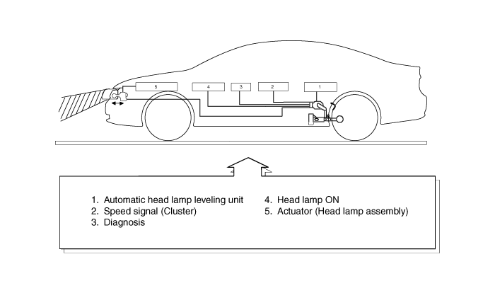
| Operation |
| 1. |
Suspension angle change resulted from vehicle''s load change. |
| 2. |
Sensor angle change. |
| 3. |
Microprocessor calculates necessary head lamp angle change amount. |
| 4. |
Sending a proper signal to head lamp leveling device and driving actuator. |
| 1. |
Ignition on |
| 2. |
Low beam on |
| 3. |
On stop : If sensor lever change is 2° and above, head lamp is operated after max. 1.5 sec. |
| 4. |
On driving : If vehicle velocity is over 4km/h(2.48mile/h),
velocity change is not over 0.8-1.6km/h(0.5 ~ 1.0mile/h) per second, and
loading condition is changed, then head lamp is operated. |
| 1. |
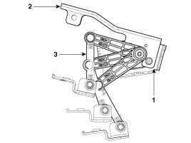
Auto head lamp leveling unit
1. Leveling unit & sensor
2. Sensor mounting bracket
3. Sensor linkage
|
| 2. |
Actuator
|

 Auto Head Lamp Leveling Unit Schematic Diagrams
Circuit Diagram ...
 Auto Head Lamp Leveling Unit Repair procedures
Inspection 1. Ignition "ON". 2. Turn on the head lamp switch. 3. Check for operation. If the aim of the head lamps changes smoothly when the head lamp leveling switch is turned. 4. If the operation does ...
Other information:
Kia Optima Hybrid (TF HEV) 2016-2020 Service Manual: Repair procedures
Fuel Pressure Test 1. Release the residual pressure in fuel line (Refer to “Release Residual Pressure in Fuel Line” in this group). When removing the fuel pump relay, a Diagnostic Trouble Code (DTC) may occur. Delete the code with the GDS after completion of “Release Residual Pressure ...
Kia Optima Hybrid (TF HEV) 2016-2020 Service Manual: Cylinder Block Repair procedures
Disassembly • Use fender covers to avoid damaging painted surfaces. • To avoid damaging the cylinder head, wait until the engine coolant temperature drops below normal temperature before removing it. • When handling a metal gasket, take care not to fold the gasket or damage the contact ...

