Kia Optima Hybrid: Automatic Transaxle Control System / Transaxle Oil Temperature Sensor Repair procedures
| Inspection |
| 1. |
Turn ignition switch OFF. |
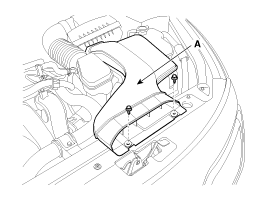
| 2. |
Remove the air duct (A).
|
| 3. |
Remove the air cleaner assembly.
|
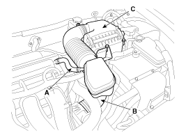

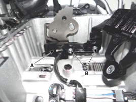
| 4. |
Remove the solenoid valve connector (A).
|
| 5. |
Measure resistance between sensor signal terminal and sensor ground terminal. |
| 6. |
Check that the resistance is within the specification. |
| Removal |
|

| 1. |
Change the shift lever to "N" range. |
| 2. |
Remove the valve body assembly.
(Refer to Hydraulic System - "Valve Body") |
| 3. |
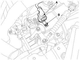
Disconnect the input & output speed sensor connector (A). |
| 4. |
Loosen the main connector bolt (B).
|
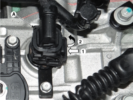
| 5. |
Disconnect the solenoid valve connector (A).
|
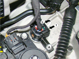
| 6. |
Remove the solenoid valve connector clip (B) after loosening a bolt and then remove the connector (A) by pushing down to it.
|
| Installation |
| 1. |
Install in the reverse order of removal. |
|
 Transaxle Oil Temperature Sensor Schematic Diagrams
Circuit Diagram ...
 Input Speed Sensor Description and Operation
Description Input speed sensor is a vital unit that measures the rate of rotation of the input shaft inside the transaxle and delivers the readings to the TCM. The sensor provides critical input data that''s ...
Other information:
Kia Optima Hybrid (TF HEV) 2016-2020 Service Manual: General Information
Precautions General Precautions Please read the following precautions carefully before performing the airbag system service. Observe the instructions described in this manual, or the airbags could accidentally deploy and cause damage or injuries. • Except when performing electrical inspections, always ...
Kia Optima Hybrid (TF HEV) 2016-2020 Service Manual: Auxiliary 12V Battery Repair procedures
Removal and Installation 1. Disconnect the battery negative terminal (B) first, then the positive terminal (A). Tightening torque : (+) terminal (A) : 7.8 ~ 9.8N.m (0.8 ~ 1.0kgf.m, 5.8 ~ 7.2lb-ft) (-) terminal (B) : 4.0 ~ 6.0N.m (0.4 ~ 0.6kgf.m, 3.0 ~ 4.4lb-ft) 2. Disconnect the vent hose (C). 3. Remove ...