Kia Optima Hybrid: Automatic Transaxle Control System / SS-A Solenoid Valve (ON/OFF) Repair procedures
Kia Optima Hybrid (TF HEV) 2016-2020 Service Manual / Automatic Transaxle System / Automatic Transaxle Control System / SS-A Solenoid Valve (ON/OFF) Repair procedures
| Inspection |
| 1. |
Turn ignition switch OFF. |
| 2. |
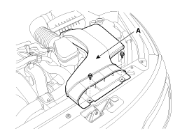
Remove the air duct (A).
|
| 3. |
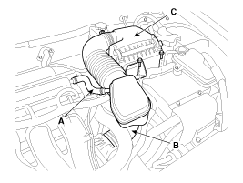
Remove the air cleaner assembly.
|
| 4. |
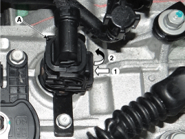
Remove the solenoid valve connector (A).
|
| 5. |
Measure resistance between signal terminal and ground terminal. |
| 6. |
Check that the resistance is within the specification. |
| Removal |
|
| 1. |
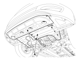
Remove the under cover (A).
|
| 2. |
Drain the coolant of hybrid motor cooling system.
(Refer to Hybrid Motor System - "Coolant") |
| 3. |
Drain the coolant of engine & transaxle cooling system.
(Refer to Engine Mechanical System - "Coolant") |
| 4. |
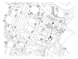
Remove the drain plug (A) and reinstall the drain plug after draining ATF totally.
|
| 5. |
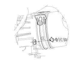
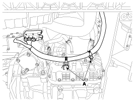
Remove the valve body wire ring fixed clip (A).
|
| 6. |
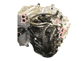
Remove the air duct (A).
|
| 7. |
Remove the air cleaner assembly.
|
| 8. |
Remove the hybrid power control unit (HPCU) assembly.
(Refer to Hybrid Control System - "HPCU (Hybrid Power Control Unit") |
| 9. |
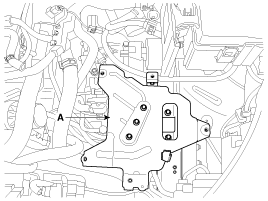
Remove the HPCU tray (A).
|
| 10. |
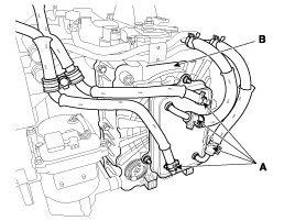
Remove the automatic transaxle oil cooler tube (A).
|
| 11. |
Remove the valve body cover bolt after removing the ATF warmer hose (A).
|
| 12. |
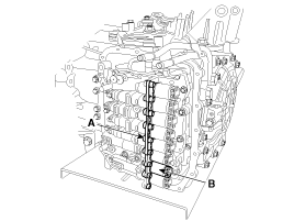
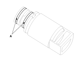
Remove the solenoid valve (B) after removing the solenoid support (A).
|
| Installation |
| 1. |
Install in the reverse order of removal.
|
 SS-A Solenoid Valve (ON/OFF) Schematic Diagrams
Circuit Diagram ...
 SS-B Solenoid Valve (ON/OFF) Description and Operation
Description The SS-B solenoid valve is attached to the valve body and is an SS-B solenoid valve that is used to change gears. ...
Other information:
Kia Optima Hybrid (TF HEV) 2016-2020 Service Manual: Catalytic Converter Description and Operation
Description The catalytic converter of the gasoline engine is a three way catalyst. It oxidizes carbon monoxide and hydrocarbons (HC), and separates oxygen from the oxides of nitrogen (NOx). ...
Kia Optima Hybrid (TF HEV) 2016-2020 Service Manual: NVLD(Natural Vacuum Leakage Detection) Description and Operation
Description NVLD(Natural Vacuum Leakage Detection) is located between the canister and the fuel tank air filter. NVLD is to detect leaks equivalent to a 0.5 mm hole in the fuel tank, canister and hoses. When the engine has been running, the temperature of the fuel in the fuel tank is raised slightly. ...
© 2025 Copyright www.koptimatfhev.com

