Kia Optima Hybrid: Steering System / Special Service Tools
| Special Service Tools |
| Tool Name / Number | IIIustration | Description |
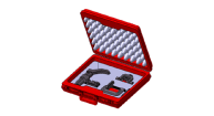
| Lower arm ball joint remover 0K545-A9100 |
| Removal of front lower arm from front axle |
| Personal Protective Equipment |
| Name | Illustration | Description |
| Insulation glove |
| Used when inspecting or working on the high voltage components [Insulation performance : 1000V / 300A or above] |
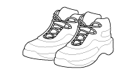
| Insulation shoes |
| Used when inspecting or working on the high voltage components |
| Insulation clothes |
| |
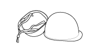
| Insulation helmet |
| |
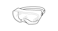
| Safety glasses |
| Used in the case below • During Removal & installation or inspection of the high voltage battery terminals or wiring, which spark might happen. • During working on the high voltage battery pack assembly. |
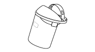
| Face shield |
| |
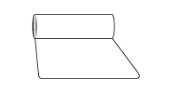
| Insulation mat |
| Putting the removed high voltage components on the insulation mat to prevent safety accidents. |
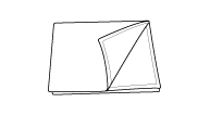
| Insulation sheet |
| Covering
the high voltage components with insulation sheet to prevent people who
don’t wear the personal protective equipment from safety accidents. |
 Specifications
Specifications ItemSpecificationTypeMotor Driven Power SteeringSteering gearTypeRack & PinionRack stroke148mm (5.82in)Steering angle(Max.)Inner40.05° ± 1.5°Outer32.95° Tightening Torques ItemTightening ...
 Troubleshooting
Troubleshooting SymptomProbable causeRemedyPlay in steeringLoose yoke plugRetightenLoose steering gear mounting boltsRetightenLoose or worn tie rod endRetighten or replace as necessarySteering wheel does ...
Other information:
Kia Optima Hybrid (TF HEV) 2016-2020 Service Manual: Components and Components Location
Component Location 1. Horn switch2. Horn relay (Engine room compartment)3. Horn (Low)4. Clock spring5. Horn (High) ...
Kia Optima Hybrid (TF HEV) 2016-2020 Service Manual: Special Service Tools
Personal Protective Equipment NameIllustrationDescriptionInsulation gloveUsed when inspecting or working on the high voltage components[Insulation performance : 1000V / 300A or above]Insulation shoesUsed when inspecting or working on the high voltage componentsInsulation clothesInsulation helmetSafety ...

