Kia Optima Hybrid: Automatic Transaxle Control System / Shift Lever Repair procedures
| Removal |
| 1. |
Disconnect the 12V battery negative (-) cable. |
| 2. |
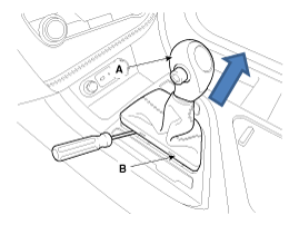
Remove the knob (A) and boots (B) by pulling the direction of arrow after removing the boots from the console upper cover.
|
| 3. |
Remove the floor console assembly.
(Refer to Body - "Console") |
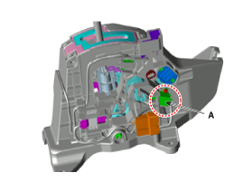
| 4. |
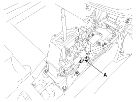
Disconnect the main connector (A).
|
| 5. |
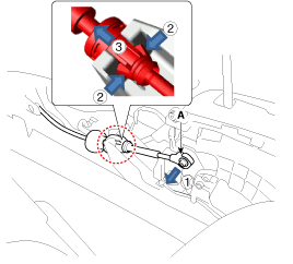
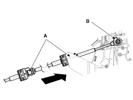
Disconnect the shift cable (A) from the shift lever.
|
| 6. |
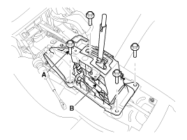
Remove the bolt (A-4) and remove the shift lever assembly (B).
|
| Installation |
| 1. |
Install in the reverse order of removal.
|
| Disassembly |
| "P" position switch replace |
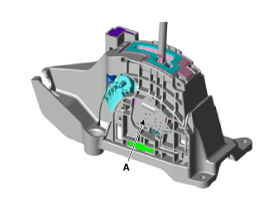
| 1. |
Remove the screw and then remove the "P" position switch (A).
|
| 2. |
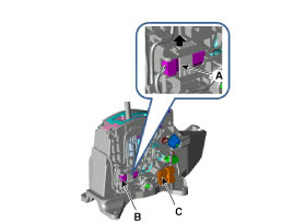
Remove the plastic bracket (A) and remove the shift lock solenoid (B). |
| 3. |
Remove the main connector (C).
|
| 4. |
Loosen the screw and remove the manual mode switch housing (A).
|
| 5. |
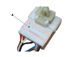
Remove the wiring fixed bracket (A) of main connector.
|
| 6. |
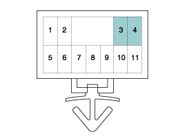
Remove the wiring of "P" position switch from the main connector. |
Check the wiring color before disconnecting the wiring.
|
| Shift lock solenoid replace |
| 1. |
Loosen the screw and remove the "P" position switch (A).
|
| 2. |
Remove the plastic bracket (A) and remove the shift lock solenoid (B). |
| 3. |
Remove the main connector (C).
|
| 4. |
Loosen the screw and remove the manual mode switch housing (A).
|
| 5. |
Remove the wiring fixed bracket (A) of main connector.
|
| 6. |
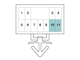
Remove the wiring of shift lock solenoid from the main connector.
|
| Manual mode switch housing replace |
| 1. |
Loosen the screw and remove the "P" position switch (A).
|
| 2. |
Remove the plastic bracket (A) and remove the shift lock solenoid (B). |
| 3. |
Remove the main connector (C).
|
| 4. |
Loosen the screw and remove the manual mode switch housing (A).
|
| 5. |
Remove the wiring fixed bracket (A) of main connector.
|
| 6. |
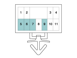
Remove the wiring of manual mode switch housing from the main connector.
|
 Shift Lever Components and Components Location
Components 1. Shift lever assembly 2. Shift cable retainer3. Shift cable assembly4. "P" position switch5. Manual mode switch housing6. Shift lock solenoid ...
 Shift Cable Components and Components Location
Components 1. Shift lever assembly3. Shift cable assembly 2. Shift cable retainer? ...
Other information:
Kia Optima Hybrid (TF HEV) 2016-2020 Service Manual: Compression Test
Compression Pressure Inspection If the there is lack of power, excessive oil consumption or poor fuel economy, measure the compression pressure. Engine may start anytime the vehicle is in READY mode.1. Warm up and stop engine. 1. Warm up and stop engine. Allow the engine to ...
Kia Optima Hybrid (TF HEV) 2016-2020 Service Manual: Temperature Control Actuator Description and Operation
Description 1. Heater unit includes mode control actuator and temperature control actuator. 2. Temperature control actuator is located at the heater unit. It regulates the temperature by the procedure as follows. Signal from control unit adjusts position of temperature door by operating temperature switch ...

