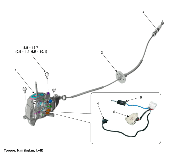
Kia Optima Hybrid: Automatic Transaxle Control System / Shift Lever Components and Components Location
| Components |

| 1. Shift lever assembly 2. Shift cable retainer 3. Shift cable assembly | 4. "P" position switch 5. Manual mode switch housing 6. Shift lock solenoid |
 Inhibitor Switch Repair procedures
Inspection • Thoroughly check connectors for looseness, poor connection, bending, corrosion, contamination, deterioration, or damage. Power Circuit Inspection 1. Disconnect the Inhibitor ...
 Shift Lever Repair procedures
Removal 1. Disconnect the 12V battery negative (-) cable. 2. Remove the knob (A) and boots (B) by pulling the direction of arrow after removing the boots from the console upper cover. 3. Remove the floor ...
Other information:
Kia Optima Hybrid (TF HEV) 2016-2020 Service Manual: CVVT Oil Control Valve (OCV) Repair procedures
Inspection 1. Turn the ignition switch OFF. 2. Disconnect the OCV connector. 3. Measure resistance between the OCV terminals 1 and 2. 4. Check that the resistance is within the specification. Specification: 6.9 ~ 7.9? [20°C(68°F)] Removal 1. Turn the ignition switch OFF and disconnect the battery negative ...
Kia Optima Hybrid (TF HEV) 2016-2020 Service Manual: Radiator Components and Components Location
Components 1. Cooling fan assembly2. Radiator assembly3. Mounting insulator4. Radiator mounting bracket5. Radiator upper hose6. Radiator lower hose7. Reservoir tank8. Over flow hose ...
