Kia Optima Hybrid: IMS (Integrated Memory) / Schematic Diagrams
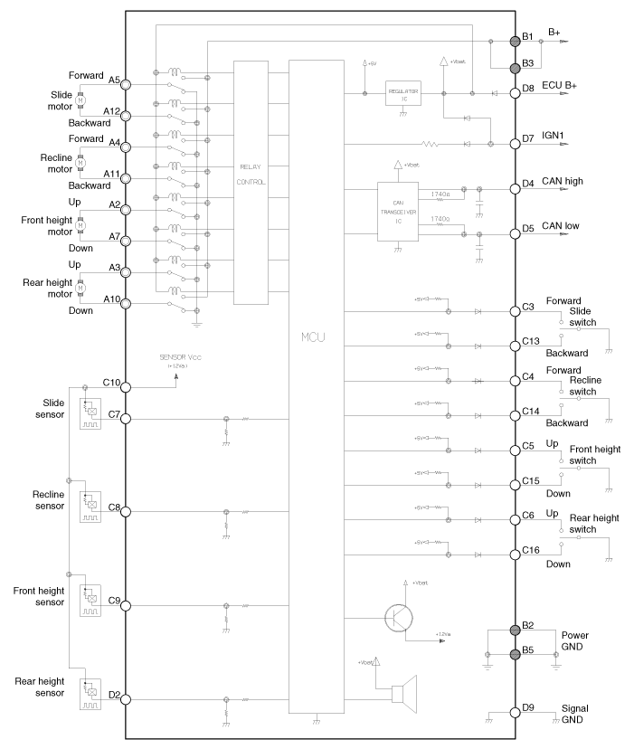
| Circuit Diagram |

| Input/Output Specification |
| Connector Pin Lay Out |

| No | Signal Name | I/O | Contents | Remark |
| A1 | - | - | - | |
| A2 | FR height motor up | O | FR height motor up output | |
| A3 | RR height motor up | O | RR height motor up output | |
| A4 | Recline motor FR | O | Recline motor FR output | |
| A5 | Slide motor FR | O | Slide motor FR output | |
| A6 | - | - | - | |
| A7 | FR height motor down | O | FR height motor down output | |
| A8 | - | - | - | |
| A9 | - | - | - | |
| A10 | RR height motor down | O | RR height motor down output | |
| A11 | Recline motor RR | O | Recline motor RR output | |
| A12 | Slide motor RR | O | Slide motor RR output | |
| B1 | GND(Power) | I | Power B+ for operating motor | |
| B2 | GND (Power) | I | Power GND for operating motor | |
| B3 | B+(Power) | I | Power B+ for operating motor | |
| B4 | - | - | - | |
| B5 | GND (Power) | I | Power GND for operating motor | |
| C1 | - | - | - | |
| C2 | - | - | - | |
| C3 | Slide FR manual switch | I | Slide FR manual switch input | On : GND |
| C4 | Recline FR manual switch | I | Recline FR manual switch input | On : GND |
| C5 | FR height up manual switch | I | FR height up manual switch input | On : GND |
| C6 | RR height up manual switch | I | RR height up manual switch input | On : GND |
| C7 | Slide motor sensor | I | Slide motor sensor input | Pulse signal |
| C8 | Recline motor sensor | I | Recline motor sensor input | Pulse signal |
| C9 | FR height motor sensor | I | FR height motor sensor input | Pulse signal |
| C10 | Sensor Vcc(Seat) | O | VCC for operating sensor | 5V |
| C11 | - | - | - | |
| C12 | - | - | - | |
| C13 | Slide RR manual switch | I | Slide RR manual switch input | ON : GND |
| C14 | Recline RR manual switch | I | Recline RR manual switch input | ON : GND |
| C15 | FR height down manual switch | I | FR height down manual switch input | ON : GND |
| C16 | RR height down manual switch | - | RR height down manual switch input | ON : GND |
| C17 | - | - | - | |
| C18 | - | - | - | |
| C19 | - | - | - | |
| C20 | - | - | - | |
| D1 | SET switch | O | SET switch | |
| D2 | RR height up sensor | I | RR height up motor sensor | Pulse signal |
| D3 | Switch 1 | O | IMS 1 switch | |
| D4 | CAN high | I/O | CAN | |
| D5 | CAN low | I/O | CAN | |
| D6 | Switch 2 | O | IMS 2 switch | |
| D7 | IGN1 | I | IGN1 input | BAT |
| D8 | B+(ECU) | I | ECU power input | BAT |
| D9 | GND(ECU) | I | ECU GND | |
| D10 | - | - | - | |
| D11 | - | - | - | |
| D12 | - | - | - | |
| D13 | - | - | - | |
| D14 | - | - | - | |
| D15 | - | - | - | |
| D16 | - | - | - |
| Communication System |

 Components and Components Location
Component Location 1. Seat Memory Unit (IMS)2. IMS control switch3. IMS driver power seat control ...
 Description and Operation
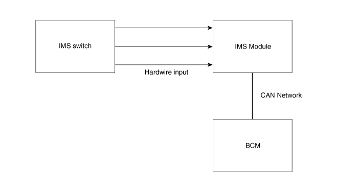
Description system outline An optimal seat position set by a driver can be memorized in Power seat unit by IMS SW, which enables restoration of seat position set by the driver despite Playing of this function ...
Other information:
Kia Optima Hybrid (TF HEV) 2016-2020 Service Manual: Rear Cross Member Repair procedures
Replacement 1. Remove the rear wheel & tire. Tightening torque: 88.3 ~ 107.9N.m(9.0 ~ 11.0kgf.m, 65.1 ~ 79.6lb-ft) Be careful not to damage the hub bolts when removing the rear wheel & tire. 2. Remove the rear lower arm. (Refer to lower arm) 3. Remove the rear shock absorber. (Refer ...
Kia Optima Hybrid (TF HEV) 2016-2020 Service Manual: Description and Operation
Description The BSD (Blind Spot Detection) system uses a radar sensor to alert the driver while driving. It senses the rear side territory of the vehicle and provides information to the driver. – BSD (Blind Spot Detection) Warning range is dependent on your vehicle speed. However, if your vehicle speed ...
