Kia Optima Hybrid: AHB(Active Hydraulic Boost) System / Rear Disc Brake Repair procedures
Kia Optima Hybrid (TF HEV) 2016-2020 Service Manual / Brake System / AHB(Active Hydraulic Boost) System / Rear Disc Brake Repair procedures
| Removal |
| 1. |
Remove the rear wheel & tire.
|
| 2. |
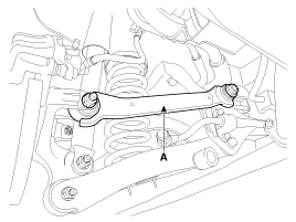
Remove the rear upper arm (A).
|
| 3. |
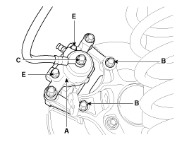
Loosen the hose eyebolt (C) and caliper mounting bolts (B), then remove the rear caliper assembly (A).
|
| 4. |
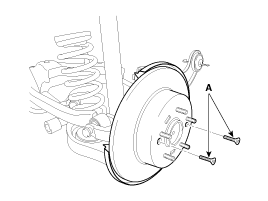
Remove the rear brake disc by loosening the screws (A).
|
| Replacement |
Rear brake pads
| 1. |
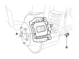
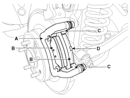
Loosen the guide rod bolt (B) and pivot the caliper (A) up out of the way.
|
| 2. |
Replace pad shim (D), pad retainers (C) and brake pads (B) in the caliper carrier (A).
|
| Inspection |
Rear Brake Disc Thickness Check
| 1. |
Check the brake pads for wear and fade. |
| 2. |
Check the brake disc for damage and cracks. |
| 3. |
Remove all rust and contamination from the surface, and
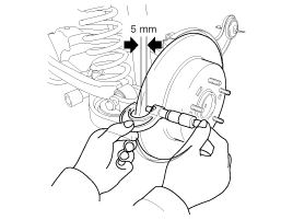
measure the disc thickness at 8 points, at least, of same distance (5mm)
from the brake disc outer circle.
|
| 4. |
If wear exceeds the limit, replace the discs and pad assembly left and right of the vehicle. |
Rear Brake Pad Check
| 1. |
Check the pad wear. Measure the pad thickness and replace it, if it is less than the specified value.
|
| 2. |
Check that grease is applied, to sliding contact points. Check for metal damage to the pad and backing.
|
Rear Brake Disc Runout Check
| 1. |
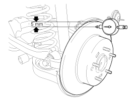
Place a dial gauge about 5mm (0.2 in.) from the outer circumference of the brake disc, and measure the runout of the disc.
|
| 2. |
If the runout of the brake disc exceeds the limit specification, replace the disc, and then measure the runout again. |
| 3. |
If the runout does not meet the limit specification, remove
the disc, turn it 180° and reinstall. Then check the runout of the
brake disc again. |
| 4. |
If the runout cannot be corrected by changing the position of the brake disc, replace the brake disc. |
| Installation |
| 1. |
Installation is the reverse of removal. |
| 2. |
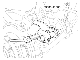
Use a SST (09581-11000) when installing the brake caliper assembly.
|
| 3. |
After installation, bleed the brake system.
(Refer to Brake system bleeding) |
|
 Rear Disc Brake Components and Components Location
Components 1. Guide rod bolt2. Bleed screw3. Caliper carrier4. Caliper body5. Inner pad shim6. Brake pad7. Pad retainer ...
Other information:
Kia Optima Hybrid (TF HEV) 2016-2020 Service Manual: Engine Clutch Control Solenoid Valve (E/C_VFS) Specifications
Specifications Direct control VFS [E/C] Control type : Normal low type Control Pressure kpa(kgf/cm?, psi)9.81 ~ 500.14(0.1 ~ 5.1, 1.42 ~ 72.54)Current value (mA)50~850 Internal resistance (?)5.1 ...
Kia Optima Hybrid (TF HEV) 2016-2020 Service Manual: Description and Operation
Description The Vehicle Information System is a Telematics service that ensures comfortable and enjoyable driving by providing safety, security, and vehicle diagnostic information, with the option of using your smartphone. The term "Telematics" is a combination of telecommunication and ...
© 2025 Copyright www.koptimatfhev.com

