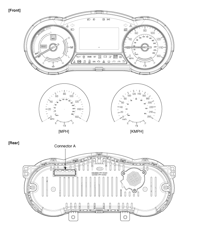
Kia Optima Hybrid: Indicators And Gauges / Instrument Cluster Components and Components Location
Kia Optima Hybrid (TF HEV) 2016-2020 Service Manual / Body Electrical System / Indicators And Gauges / Instrument Cluster Components and Components Location
| Components |


Connector Pin Information
| No. | Description | No. | Description |
| 1 | - | 21 | Immobilizer input |
| 2 | Heated wheel indicator input | 22 | Fuel sendor (+) input |
| 3 | Aig bag (+) input | 23 | Trip switch 2 (+) input (Trip button) |
| 4 | Speed output (-) (4P outpput) | 24 | Rheostat switch up input |
| 5 | Oil pressure switch input (-) | 25 | Rheostat switch down input |
| 6 | - | 26 | Low washer level input (-) |
| 7 | - | 27 | - |
| 8 | Trip switch 1 (+) input (Cruise button) | 28 | Tail lamp input (Illumination (+)) |
| 9 | - | 29 | C CAN High |
| 10 | - | 30 | C CAN Low |
| 11 | - | 31 | B CAN Low |
| 12 | - | 32 | B CAN High |
| 13 | Trip switch (-) input | 33 | - |
| 14 | Signal 1 ground | 34 | AT R position output (+) |
| 15 | Fuel sendor (-) input | 35 | AT S positon output (+) |
| 16 | - | 36 | AT D position output (+) |
| 17 | Battery (+) | 37 | AT Pposition output (+) |
| 18 | IGN1 | 38 | AT Nposition output (+) |
| 19 | - | 39 | Detent output (+) |
| 20 | Signal 3 ground | 40 | Illumination (-) output |
 Components and Components Location
Component Location 1. Instrument cluster assembly2. Seat belt switch3. Vehicle speed sensor4. Engine coolant temperature sender5. Oil pressure switch6. Brake fluid level warning switch7. Parking brake ...
 Instrument Cluster Description and Operation
Description Cluster Network Diagram ECMEngine Control ModuleHCUHybrid Control ModuleMCUMotor Control ModuleBMSBattery Management SystemTCMTransaxle Control ModuleEBSElectronic Brake SystemOPUOil ...
Other information:
Kia Optima Hybrid (TF HEV) 2016-2020 Service Manual: Front Hub / Knuckle Components and Components Location
Components 1. Driveshaft nut2. Brake disc3. Hub4. Wheel bearing5. Snap ring6. Dust cover7. Knuckle8. Driveshaft ...
Kia Optima Hybrid (TF HEV) 2016-2020 Service Manual: Fuel Tank Pressure Sensor (FTPS) Specifications
Specification Pressure [kPa (kgf/cm?, in H2O)Output Voltage (V)-6.67 (-0.068, -26.8)0.502.5+6.67 (0.068, 26.8)4.5 ...
© 2025 Copyright www.koptimatfhev.com
