Kia Optima Hybrid: Driveshaft and axle / High Voltage Shut-off Procedures
| High Voltage Shut-off Procedures |
Be sure to read and follow the “General Safety Information
and Caution” before doing any work related with the high voltage
system. Failure to follow the safety instructions may result in serious
electrical injuries. |
|
| 1. |
Turn the ignition switch OFF and disconnect the auxiliary 12V battery negative (-) terminal. |
| 2. |
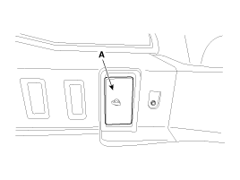
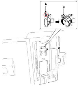
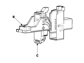
Remove the safety plug.
|
| 3. |
Wait for more than 5 minutes so that the capacitor in the high voltage system can be fully discharged. |
| 4. |
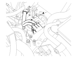
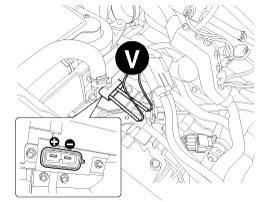
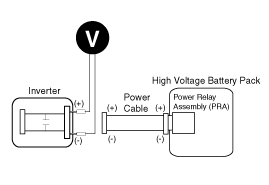
Measure the voltage between the inverter terminals to check that the capacitor in the inverter is discharged completely
|
 General Safety Information and Caution
Safety Precaution Since hybrid vehicles contain a high voltage battery, if the high voltage system or vehicles are handled incorrectly, this might lead to a serious accidents like electric ...
 Specifications
Specification EngineT/MJoint typeMax. permissible angleOuterInnerOuterInnerGasoline 2.4M/TBJ#95TJ#9545°21°A/TBJ#95TJ#9545°21° Tightening torque ItemN.mkgf.mIb.ftFrontWheel nut88.2 ~ 107.89.0 ~ 11.065.0 ...
Other information:
Kia Optima Hybrid (TF HEV) 2016-2020 Service Manual: Electric Parking Brake (EPB) Components and Components Location
Components 1. EPB Unit2. EPB Switch3. Brake Caliper 4. EPB Warning Lamp5. AUTO HOLD Lamp ...
Kia Optima Hybrid (TF HEV) 2016-2020 Service Manual: Rear Door Repair procedures
Replacement Door Trim Replacement • Be careful not to scratch the door trim and other parts. • Put on gloves to protect your hands. 1. After loosening the mounting screws, then remove the rear door trim (A). 2. Disconnect the inside handle cage (A). 3. Disconnect the connector (A). ...


