Kia Optima Hybrid: Controller / Heater & A/C Control Unit(Dual) Components and Components Location
Kia Optima Hybrid (TF HEV) 2016-2020 Service Manual / Heating,Ventilation, Air Conditioning / Controller / Heater & A/C Control Unit(Dual) Components and Components Location
| Components (1) |
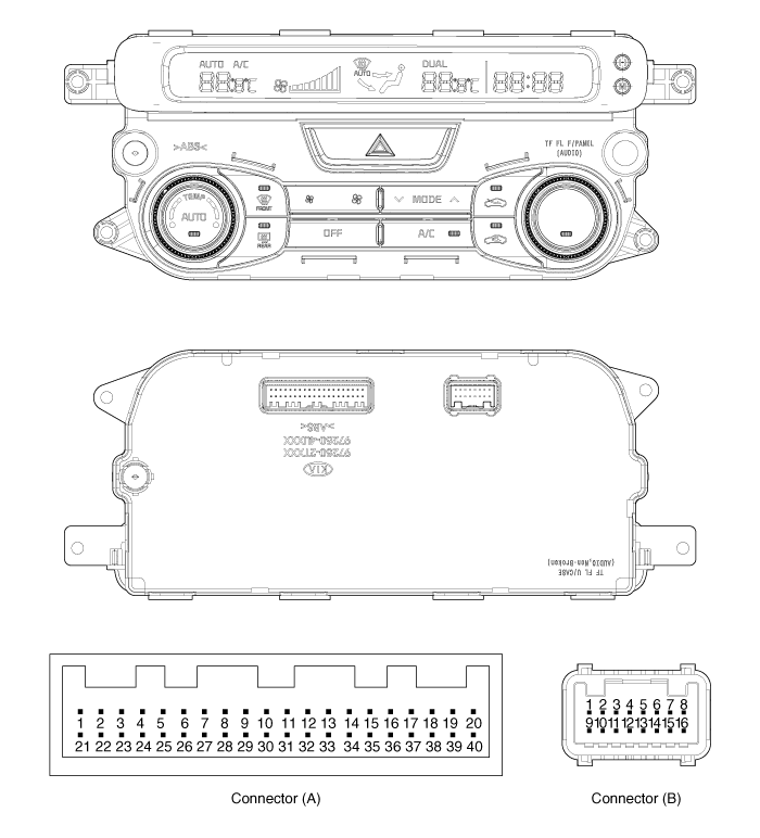
| Control Panel (Dual A/C & Heater Controller - A) |

Connector pin function (1)
| Connector | PIN NO. | Function | Connector | PIN NO. | Function |
| Connector (A) | 1 | ILL+(TAIL) | Connector (A) | 29 | ECV (+) |
| 2 | SENSOR REF (+5V) | 30 | ECV (-) (GND) | ||
| 3 | HAZARD SIGNAL | 31 | PHOTO SENSOR (-) -LEFT | ||
| 4 | ACC | 32 | PHOTO SENSOR (-) -RIGHT | ||
| 5 | MODE ACT''R (VENT) | 33 | HTD | ||
| 6 | MODE ACT''R (DEF) | 34 | REAR DEFOG S/W | ||
| 7 | MODE ACT''R F/B | 35 | C-CAN | ||
| 8 | INTAKE ACT''R (FRE) | 36 | - | ||
| 9 | INTAKE ACT''R (REC) | 37 | PTC ON SIGNAL | ||
| 10 | INTAKE ACT''R F/B | 38 | PTC RELAY 2 | ||
| 11 | TEMP ACT''R (COOL)-DIVER | 39 | PTC RELAY 3 | ||
| 12 | TEMP ACT''R (WARM)-DIVER | 40 | SENSOR GND | ||
| 13 | TEMP ACT''R F/B-DIVER | Connector (B) | 1 | GND | |
| 14 | TEMP ACT''R (COOL)-PASSENGER | 2 | - | ||
| 15 | TEMP ACT''R (WARM)-PASSENGER | 3 | DEF ACT''R (CLOSE) | ||
| 16 | TEMP ACT''R F/B-PASSENGER | 4 | DEF ACT''R (OPEN) | ||
| 17 | C_CAN HIGH | 5 | DEF ACT''R F/B | ||
| 18 | C_CAN LOW | 6 | HUMIDITY (PWM) | ||
| 19 | DETENT OUT(+) | 7 | - | ||
| 20 | ILL-(RHEO) | 8 | IGN2 | ||
| 21 | ION SIGNAL | 9 | GND | ||
| 22 | CLEAN SIGNAL | 10 | - | ||
| 23 | IONIZER DIAGNOSIS | 11 | BLOWER MOTOR (+) | ||
| 24 | - | 12 | FET (GATE) | ||
| 25 | - | 13 | FET (DRAIN F/B) | ||
| 26 | AMB SENSOR (+) | 14 | ISG-DC | ||
| 27 | - | 15 | IGN1 | ||
| 28 | EVAP SENSOR (+) | 16 | BATT |
| Components (2) |
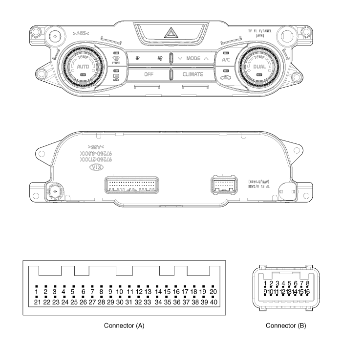
| Control Panel (Dual A/C & Heater Controller - B) |

Connector pin function (2)
| Connector | PIN NO. | Function | Connector | PIN NO. | Function |
| Connector (A) | 1 | ILL+(TAIL) | Connector (A) | 29 | ECV (+) |
| 2 | SENSOR REF (+5V) | 30 | ECV (-) (GND) | ||
| 3 | HAZARD SIGNAL | 31 | PHOTO SENSOR (-) -LEFT | ||
| 4 | - | 32 | PHOTO SENSOR (-) -RIGHT | ||
| 5 | MODE ACT''R (VENT) | 33 | HTD | ||
| 6 | MODE ACT''R (DEF) | 34 | REAR DEFOG S/W | ||
| 7 | MODE ACT''R F/B | 35 | C-CAN | ||
| 8 | INTAKE ACT''R (FRE) | 36 | - | ||
| 9 | INTAKE ACT''R (REC) | 37 | PTC ON SIGNAL | ||
| 10 | INTAKE ACT''R F/B | 38 | PTC RELAY 2 | ||
| 11 | TEMP ACT''R (COOL)-DIVER | 39 | PTC RELAY 3 | ||
| 12 | TEMP ACT''R (WARM)-DIVER | 40 | SENSOR GND | ||
| 13 | TEMP ACT''R F/B-DIVER | Connector (B) | 1 | GND | |
| 14 | TEMP ACT''R (COOL)-PASSENGER | 2 | - | ||
| 15 | TEMP ACT''R (WARM)-PASSENGER | 3 | DEF ACT''R (CLOSE) | ||
| 16 | TEMP ACT''R F/B-PASSENGER | 4 | DEF ACT''R (OPEN) | ||
| 17 | C_CAN HIGH | 5 | DEF ACT''R F/B | ||
| 18 | C_CAN LOW | 6 | HUMIDITY (PWM) | ||
| 19 | DETENT OUT(+) | 7 | - | ||
| 20 | ILL-(RHEO) | 8 | IGN2 | ||
| 21 | ION SIGNAL | 9 | GND | ||
| 22 | CLEAN SIGNAL | 10 | - | ||
| 23 | IONIZER DIAGNOSIS | 11 | BLOWER MOTOR (+) | ||
| 24 | MM_CAN HIGH | 12 | FET (GATE) | ||
| 25 | MM_CAN LOW | 13 | FET (DRAIN F/B) | ||
| 26 | AMB SENSOR (+) | 14 | ISG-DC | ||
| 27 | - | 15 | IGN1 | ||
| 28 | EVAP SENSOR (+) | 16 | BATT |
 Controller
...
 Heater & A/C Control Unit(Dual) Repair procedures
Self Diagnosis 1. Self-diagnosis process 2. How to read self-diagnostic code After the display panel flickers three times every 0.5 second, the corresponding fault code flickers on the setup temperature ...
Other information:
Kia Optima Hybrid (TF HEV) 2016-2020 Service Manual: General Safety Information and Caution
Safety Precaution Since hybrid vehicles contain a high voltage battery, if the high voltage system or vehicles are handled incorrectly, this might lead to a serious accidents like electric shock and electric leakage. • Be sure to shut off the high voltage by removing the ...
Kia Optima Hybrid (TF HEV) 2016-2020 Service Manual: ESC OFF Switch Description and Operation
Description 1. The ESC OFF switch is for the user to turn off the ESC system. 2. The ESC OFF lamp is on when ESC OFF switch is engaged. ...
© 2025 Copyright www.koptimatfhev.com
