Kia Optima Hybrid: Engine Control System / Heated Oxygen Sensor (HO2S) Repair procedures
| Inspection |
| 1. |
Turn the ignition switch OFF. |
| 2. |
Disconnect the HO2S connector. |
| 3. |
Measure resistance between the HO2S terminals 4 and 5 [B1/S1].
Measure resistance between the HO2S terminals 3 and 4 [B1/S2]. |
| 4. |
Check that the resistance is within the specification.
HO2S [Bank 1/Sensor 1] (Linear type)
HO2S [Bank 1/Sensor 2] (Binary type)
|
| Removal |
| 1. |
Turn the ignition switch OFF and disconnect the battery negative (-) terminal. |
| 2. |
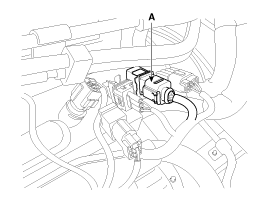
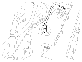
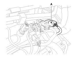
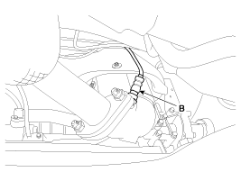
Disconnect the connector (A), and then remove the sensor (B).
[Bank 1 / Sensor 1]
[Bank 1 / Sensor 2]
|
| Installation |
|
|
| 1. |
Install in the reverse order of removal.
|
 Heated Oxygen Sensor (HO2S) Schematic Diagrams
Circuit Diagram ...
 Accelerator Position Sensor (APS) Description and Operation
Description Accelerator Position Sensor (APS) is installed on the accelerator pedal module and detects the rotation angle of the accelerator pedal. The APS is one of the most important sensors in engine ...
Other information:
Kia Optima Hybrid (TF HEV) 2016-2020 Service Manual: Windshield Deicer Repair procedures
Inspection 1. Remove the cowl top cover. (Refer to the wiper) 2. Disconnect the windshield deicer connector (A) from the wiper motor linkage. 3. Check for continuity between the terminals of deicer lines. 4. Turn the ignition switch ON and the windshield deicer switch ON, then measure the voltage between ...
Kia Optima Hybrid (TF HEV) 2016-2020 Service Manual: Front Bumper Repair procedures
Replacement • Put on gloves to protect your hands. • Use a plastic panel removal tool to remove interior trim pieces to protect from marring the surface. • Take care not to bend or scratch the cover and other parts. 1. After loosening the mounting bolts and clips, then remove the ...


