Kia Optima Hybrid: Body Dimensions / General Information
| General |
| 1. |
Basically, all measurements in this manual are taken with a tracking gauge. |
| 2. |
When a measuring tape is used, check to be sure there is no elongation, twisting or bending. |
| 3. |
For measuring dimensions, both projected dimension and actual-measurement dimension are used in this manual. |
| Measurement Method |
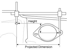
| Projected Dimensions |
| 1. |
These are the dimensions measured when the measurement
points are projected into the reference plane, and are the reference
dimensions used for body alterations. |
| 2. |
If the length of the tracking gauge probes is adjustable,
make the measurement by lengthening one probe by the amount equivalent
to the difference in height of the two surfaces.
|
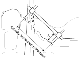
| Actual-Measurement Dimensions |
| 1. |
These dimensions indicate the actual linear distance between
measurement points, and are the reference dimensions for use if a
tracking gauge is used for measurement. |
| 2. |
Measure by first adjusting both probes to the same length (A=A'').
|
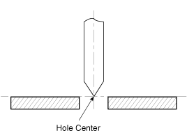
| Measurement Point |
| 1. |
Measurements should be taken at the hole center.
|
 Body Dimensions
...
 Front Body Body Repair
Front Body A Hood hinge mounting hole (O13)Fender apron upper inner panel tooling hole (O6.6)Front suspension mounting hole (O11)Cowl panel tooling hole (O8)Front pillar cornerFront pillar corner Front ...
Other information:
Kia Optima Hybrid (TF HEV) 2016-2020 Service Manual: Description and Operation
Description Tread Lamp – Tire Under Inflation / Leak Warning. 1. Turn on condition • When tire pressure is below allowed threshold • When rapid leak is detected by the sensor. 2. Turn off condition • When tire pressure is above(warning threshold + hysteresis). • When tire pressure is above ...
Kia Optima Hybrid (TF HEV) 2016-2020 Service Manual: Blind Spot Detection Indicator Repair procedures
Removal 1. Disconnect the negative (-) battery terminal. 2. Remove the mirror (C) from the mirror holder after disconnecting the heater connector (A) and BSD warning connector (B). 3. Remove the BSD warning lamp (A). Installation 1. Install the BSD warning lamp and mirror. 2. Connect the negative (-) ...


