Kia Optima Hybrid: Cylinder Head Assembly / CVVT & Camshaft Repair procedures
| Removal |
| 1. |
Remove the cylinder head cover. |
| 2. |
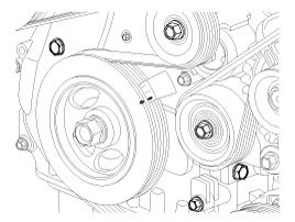
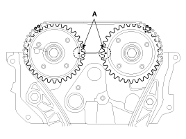
Set No.1 cylinder to TDC/compression.
|
| 3. |
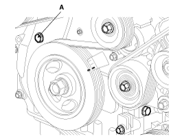
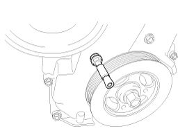
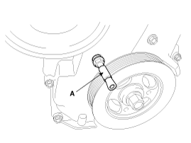
Remove the bolt (A) from the service hole in the timing chain
cover. It might be required to run a M8X1.25 tap in the hole to clean
out the lock-tight (sealer) on the threads.
|
| 4. |
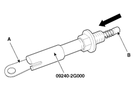
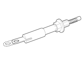
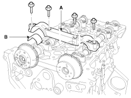
Pull and turn the loop (A) on the SST 09240-2G000 to allow
the spring loaded shaft (B) to be pulled (locked) against the spring.
Add a small amount of light lubricant to the threads of the tool and
then thread it into the hole in the timing cover until you can feel it
hit the tensioner. Then thread the tool back out about one turn.
|
| 5. |
Turn the loop to unlock the tool.
|
| 6. |
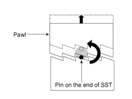
Slowly turn the tool counterclockwise. Depending on where the
pin on the tool is located, a few clicks may be heard as the pin moves
over the pawl and shaft. As you turn, you should be able to feel the
spring loaded pawl being lifted. Once lifting the pawl, tighten the lock
nut (A) and lift the chain and cam gear onto the cam.
|
| 7. |
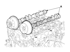
Remove the camshaft.
|
| 8. |
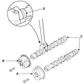
Disconnect the intake CVVT assembly(A) and exhaust CVVT assembly(B) from camshaft(C).
|
| Installation |
| 1. |
Install the intakeCVVT assembly(A), exhaust CVVT assembly(B) and camshaft(C).
|
| 2. |
Install the camshafts.
|
| 3. |
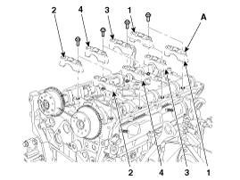
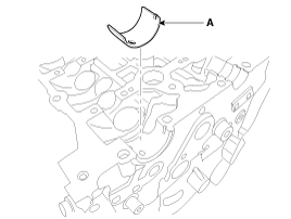
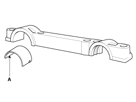
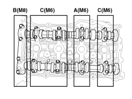
Install camshaft bearing caps (A) in their proper locations.
Tightening order
Group A > Group B > Group C.
|
| 4. |
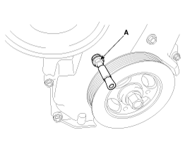
Disconnect the SST(A) (09240-2G000).
|
| 5. |
Install the service hole bolt of the timing chain cover.
|
| 6. |
Install the cylinder head cover. |
 CVVT & Camshaft Description and Operation
Description Continuous Variable Valve Timing (CVVT) system advances or retards the valve timing of the intake and exhaust valve in accordance with the ECM control signal which is calculated by the engine ...
 Cylinder Head Components and Components Location
Components 1. Camshaft bearing cap2. Camshaft front bearing cap3. Exhaust camshaft4. Intake camshaft5. Exhaust CVVT assembly6. Intake CVVT assembly7. Exhaust camshaft upper bearing8. Exhaust camshaft lower ...
Other information:
Kia Optima Hybrid (TF HEV) 2016-2020 Service Manual: NVLD(Natural Vacuum Leakage Detection) Description and Operation
Description NVLD(Natural Vacuum Leakage Detection) is located between the canister and the fuel tank air filter. NVLD is to detect leaks equivalent to a 0.5 mm hole in the fuel tank, canister and hoses. When the engine has been running, the temperature of the fuel in the fuel tank is raised slightly. ...
Kia Optima Hybrid (TF HEV) 2016-2020 Service Manual: Evaporator Temperature Sensor Repair procedures
Inspection 1. Ignition "OFF" 2. Disconnect evaporator temperature sensor. 3. Using the multi-tester, Measure resistance between terminal "1" and "2" of evaporator temperature sensor. Specification Evaporator coretemperature[°C(°F)]Resistance[K?]-10 / (14)43.350 / (32)27.6210 / (50)18.0720 / (68)12.1130 ...

