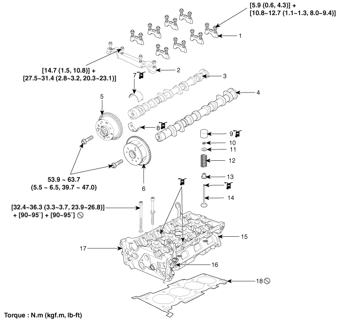
Kia Optima Hybrid: Cylinder Head Assembly / Cylinder Head Components and Components Location
| Components |

| 1. Camshaft bearing cap 2. Camshaft front bearing cap 3. Exhaust camshaft 4. Intake camshaft 5. Exhaust CVVT assembly 6. Intake CVVT assembly | 7. Exhaust camshaft upper bearing 8. Exhaust camshaft lower bearing 9. MLA (Mechanical lash adjuster) 10. Retainer lock 11. Retainer 12. Valve spring | 13. Valve stem seal 14. Valve 15. Cylinder head 16. Intake OCV (Oil control valve) 17. Exhaust OCV (Oil control valve) 18. Cylinder head gasket |
 CVVT & Camshaft Repair procedures
Removal 1. Remove the cylinder head cover. 2. Set No.1 cylinder to TDC/compression. a. Turn the crankshaft pulley and align its groove with the timing mark "T" of the lower timing chain cover. b. Check ...
 Cylinder Head Repair procedures
Removal • Use fender covers to avoid damaging painted surfaces. • To avoid damaging the cylinder head, wait until the engine coolant temperature drops below normal temperature before ...
Other information:
Kia Optima Hybrid (TF HEV) 2016-2020 Service Manual: High Voltage Shut-off Procedures
High Voltage Shut-off Procedures Be sure to read and follow the “General Safety Information and Caution” before doing any work related with the high voltage system. Failure to follow the safety instructions may result in serious electrical injuries. • High voltage components: ...
Kia Optima Hybrid (TF HEV) 2016-2020 Service Manual: General Safety Information and Caution
Safety Precaution Since hybrid vehicles contain a high voltage battery, if the high voltage system or vehicles are handled incorrectly, this might lead to a serious accidents like electric shock and electric leakage. • Be sure to shut off the high voltage by removing the ...
