Kia Optima Hybrid: Cooling System / Coolant Repair procedures
| Refilling And Bleeding |
Never remove the radiator cap when the engine is hot. Serious
scalding could be caused by hot fluid under high pressure escaping from
the radiator. |
When pouring engine coolant, be sure to shut the relay box
lid and not to let coolant spill on the electrical parts or the paint.
If any coolant spills, rinse it off immediately. |
| 1. |
Make sure the engine and radiator are cool to the touch. |
| 2. |
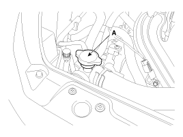
Remove radiator cap (A).
|
| 3. |
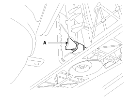
Loosen the drain plug (A), and drain the coolant.
|
| 4. |
Tighten the radiator drain plug securely. |
| 5. |
After draining engine coolant in the reservoir tank, clean the tank. |
| 6. |
Fill the radiator with water through the radiator cap and tighten the cap.
|
| 7. |
Start the engine and allow to come to normal operating
temperature. Wait for the cooling fans to turn on several times.
Accelerate the engine to aid in purging trapped air. Shut engine off. |
| 8. |
Wait until the engine is cool. |
| 9. |
Repeat steps 1 to 8 until the drained water runs clear. |
| 10. |
Fill fluid mixture with coolant and water (55~60%) (except
for North America, Europe and China : 45~50%) slowly through the
radiator cap. Push the upper/lower hoses of the radiator so as bleed air
easily.
|
| 11. |
Start the engine and run until coolant circulates.
When the cooling fan operates and coolant circulates, refill coolant through the radiator cap. |
| 12. |
Repeat 11 until the cooling fan 3 ~ 5 times and bleed air sufficiently out of the cooling system. |
| 13. |
Install the radiator cap and fill the reservoir tank to the "MAX" (or "F") line with coolant. |
| 14. |
Run the vehicle under idle until the cooling fan operates 2 ~ 3 times. |
| 15. |
Stop the engine and wait coolant gets cool. |
| 16. |
Repeat 10 to 15 until the coolant level doesn''t fall any more, bleed air out of the cooling system.
|
 Troubleshooting
Engine Overheat Troubleshooting Inspection RemedyVisual inspectionInspect for shortage of coolant in reservoir tank .Reinspect after replenishing coolant.Inspect for coolant pollution after removing radiator ...
 Radiator Components and Components Location
Components 1. Cooling fan assembly2. Radiator assembly3. Mounting insulator4. Radiator mounting bracket5. Radiator upper hose6. Radiator lower hose7. Reservoir tank8. Over flow hose ...
Other information:
Kia Optima Hybrid (TF HEV) 2016-2020 Service Manual: General Safety Information and Caution
Safety Precaution Since hybrid vehicles contain a high voltage battery, if the high voltage system or vehicles are handled incorrectly, this might lead to a serious accidents like electric shock and electric leakage. • Be sure to shut off the high voltage by removing the ...
Kia Optima Hybrid (TF HEV) 2016-2020 Service Manual: Components and Components Location
Component Location 1. Automatic transaxle assembly 2. Machanical oil Pump assembly (MOP)3. Valve body assembly4. ATF Warmer5. Electric oil pump (EOP) ...


