Kia Optima Hybrid: BCM (Body Control Module) / Body Control Module (BCM) Schematic Diagrams
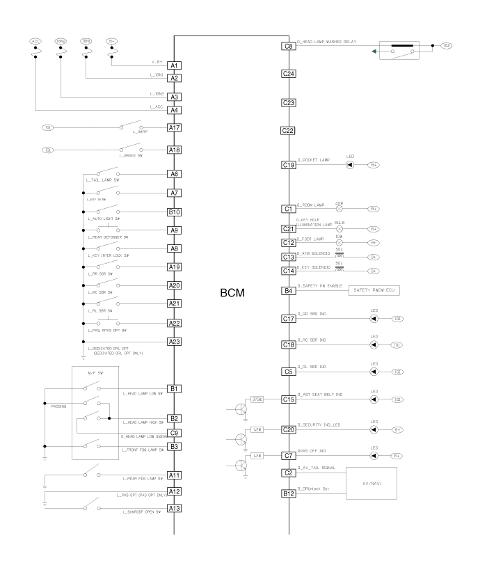
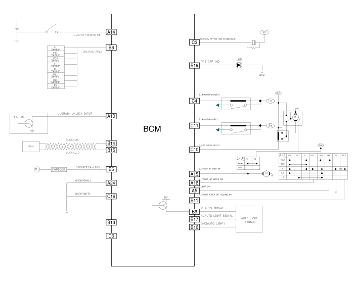
| Circuit Diagram |
 Body Control Module (BCM) Components and Components Location
Components Connector Pin Information No.Connector A (24pin)Connector B (20pin)Connector C (24pin)1Battery (+)Head lamp low beam switchRoom lamp2IGN 1Head lamp high beam switchAV tail signal3IGN 2Front ...
 Body Control Module (BCM) Description and Operation
Description CAN Communication Network Function 1. Wiper Control – Front Wiper Control Function 2. Warning Control – Driver Seat Belt Reminder Control Function – Assist Seat Belt Reminder Control ...
Other information:
Kia Optima Hybrid (TF HEV) 2016-2020 Service Manual: Rain Sensor Repair procedures
Inspection Rain Sensing Wiper 1. In IGN2 ON state, if auto switch input (LIN communication) is ON then both wiper low relay and wiper high relay outputs are controlled by the rain sensor input signal. 2. If the wiper switch has been left in automatic mode with the vehicle ignition OFF, and then the vehicle ...
Kia Optima Hybrid (TF HEV) 2016-2020 Service Manual: Troubleshooting
Troubleshooting Vehicle inspection SYMPTOM CHART SymptomSuspect AreaRemedy (See page)Squeak or grunt-noise from the front suspension, occurs more in cold ambient temperatures-more noticeable over rough roads or when turningFront stabilizer barUnder these conditions, the noise is acceptable.Clunk-noise ...