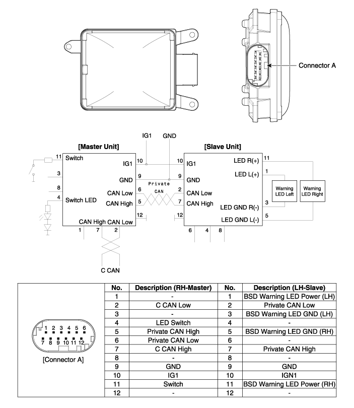
Kia Optima Hybrid: Blind Spot Detection System / Blind Spot Detection Unit Schematic Diagrams
| Circuit Diagram |

 Repair procedures
Diagnosis With GDS 1. BSD system defects can be quickly diagnosed with the GDS. GDS operates actuator quickly to monitor, input/output value and self diagnosis. 2. Connect the cable of GDS to the data ...
 Blind Spot Detection Unit Repair procedures
Removal Blind spot detection (BSD) unit 1. Disconnect the negative (-) battery. Be careful when removing the blind spot detection unit. The bracket may break off from the bumper. 2. Remove ...
Other information:
Kia Optima Hybrid (TF HEV) 2016-2020 Service Manual: Rear Door Repair procedures
Replacement Door Trim Replacement • Be careful not to scratch the door trim and other parts. • Put on gloves to protect your hands. 1. After loosening the mounting screws, then remove the rear door trim (A). 2. Disconnect the inside handle cage (A). 3. Disconnect the connector (A). ...
Kia Optima Hybrid (TF HEV) 2016-2020 Service Manual: Electric A/C compressor Specifications
Specification ModelESC33i MotroBLDC MotorControl TypeCANCompression TypeScrollCapacity33cc/revOperating Voltage Range190~320VRated Voltage288VMount TypeEngine Mounting, 6 Point Mounting ...
