Kia Optima Hybrid: SRSCM / Schematic Diagrams
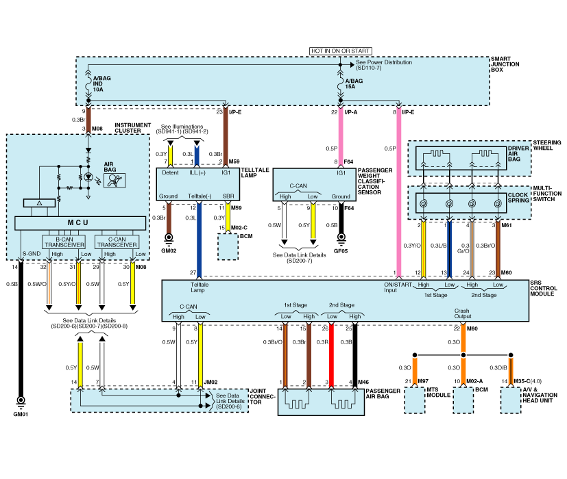
| Circuit Diagram (1) |

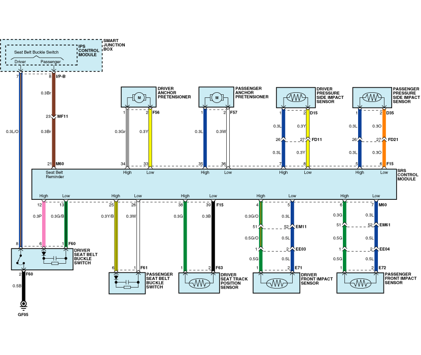
| Circuit Diagram (2) |

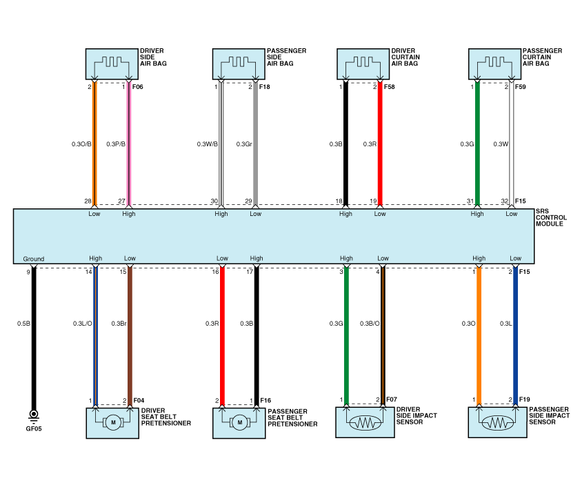
| Circuit Diagram (3) |

| SRSCM Connector Terminal |

| Pin | Function (Connector A) | Pin | Function (Connector B) | ||
| 1 | P | Smart Junction Box (Fuse - A/BAG) | 1 | O | Passenger Side Impact Sensor (High) |
| 2 | - | - | 2 | L | Passenger Side Impact Sensor (Low) |
| 3 | - | - | 3 | G | Driver Side Impact Sensor (High) |
| 4 | G/O | Driver Front Impact Sensor (High) | 4 | B/O | Driver Side Impact Sensor (Low) |
| 5 | L | Driver Front Impact Sensor (Low) | 5 | L | Passenger Pressure Side Impact Sensor (High) |
| 6 | G | Passenger Front Impact Sensor(High) | 6 | O | Passenger Pressure Side Impact Sensor (Low) |
| 7 | L | Passenger Front Impact Sensor(Low) | 7 | L | Driver Pressure Side Impact Sensor(High) |
| 8 | Y | C-CAN (Low) | 8 | Y | Driver Pressure Side Impact Sensor (Low) |
| 9 | W | C-CAN (High) | 9 | B | Ground (GF05) |
| 10 | - | - | 10 | - | - |
| 11 | - | - | 11 | - | - |
| 12 | Y/O | Driver Air Bag (1st Stage - High) | 12 | P | Driver Seat Belt Buckle Switch (High) |
| 13 | L/B | Driver Air Bag (1st Stage - Low) | 13 | G/B | Driver Seat Belt Buckle Switch (Low) |
| 14 | Br/O | Passenger Air Bag (1st Stage - Low) | 14 | L/O | Driver Seat Belt Pretensioner (High) |
| 15 | Br | Passenger Air Bag(1st Stage - High) | 15 | Br | Driver Seat Belt Pretensioner (Low) |
| 16 | - | - | 16 | R | Passenger Seat Belt Pretensioner(Low) |
| 17 | - | - | 17 | B | Passenger Seat Belt Pretensioner(High) |
| 18 | - | - | 18 | B | Driver Curtain Air Bag (High) |
| 19 | - | - | 19 | R | Driver Curtain Air Bag (Low) |
| 20 | - | - | 20 | - | - |
| 21 | Br | Smart Junction Box(IPS Control Module) | 21 | - | - |
| 22 | O | Crash Signal Output : MTS Module, BCM, A/V &Navigation Head Unit | 22 | - | - |
| 23 | Br/O | Driver Air Bag (2nd Stage - Low) | 23 | - | - |
| 24 | Gr/O | Driver Air Bag (2nd Stage - High) | 24 | - | - |
| 25 | B | Passenger Air Bag(2nd Stage - High) | 25 | Y/B | Passenger Seat Belt Buckle Switch (High) |
| 26 | R | Passenger Air Bag(2nd Stage - Low) | 26 | W | Passenger Seat Belt Buckle Switch (Low) |
| 27 | L | Telltale Lamp (-) | 27 | P/B | Driver Side Air Bag (High) |
| 28 | O/B | Driver Side Air Bag (Low) | |||
| 29 | Gr | Passenger Side Air Bag (Low) | |||
| 30 | W/B | Passenger Side Air Bag (High) | |||
| 31 | G | Passenger Curtain Air Bag (High) | |||
| 32 | W | Passenger Curtain Air Bag (Low) | |||
| 33 | Y | Driver Anchor Pretensioner (Low) | |||
| 34 | Gr | Driver Anchor Pretensioner (High) | |||
| 35 | L | Passenger Anchor Pretensioner(High) | |||
| 36 | W | Passenger Anchor Pretensioner(Low) | |||
| 37 | - | - | |||
| 38 | G | Driver Seat Track Position Sensor(High) | |||
| 39 | B | Driver Seat Track Position Sensor(Low) | |||
 Weight Classification System (WCS) Repair procedures
Removal 1. Disconnect the battery negative cable, and wait for at least three minutes before beginning work. 2. Remove the front passenger seat assembly. (Refer to the Body group - "Seat") 3. Remove the ...
 Airbag Module
...
Other information:
Kia Optima Hybrid (TF HEV) 2016-2020 Service Manual: Description and Operation
Description The ECM (Electro Chromatic inside rear view Mirror) is for dimming the reflecting light from a vehicle behind at night, Preventing glare from the light. The forward facing sensor detects brightness of the surroundings, while the rearward looking sensor detects the strength of the reflecting ...
Kia Optima Hybrid (TF HEV) 2016-2020 Service Manual: Components and Components Location
Components Location 1. Drive shaft2. Lower arm3. Front disk4. Front strut assembly5. Steering gearbox6. Front stabilizer bar7. Sub frame ...
© 2025 Copyright www.koptimatfhev.com
