Kia Optima Hybrid: Automatic Transaxle Control System / Inhibitor Switch Schematic Diagrams
| Circuit Diagram |
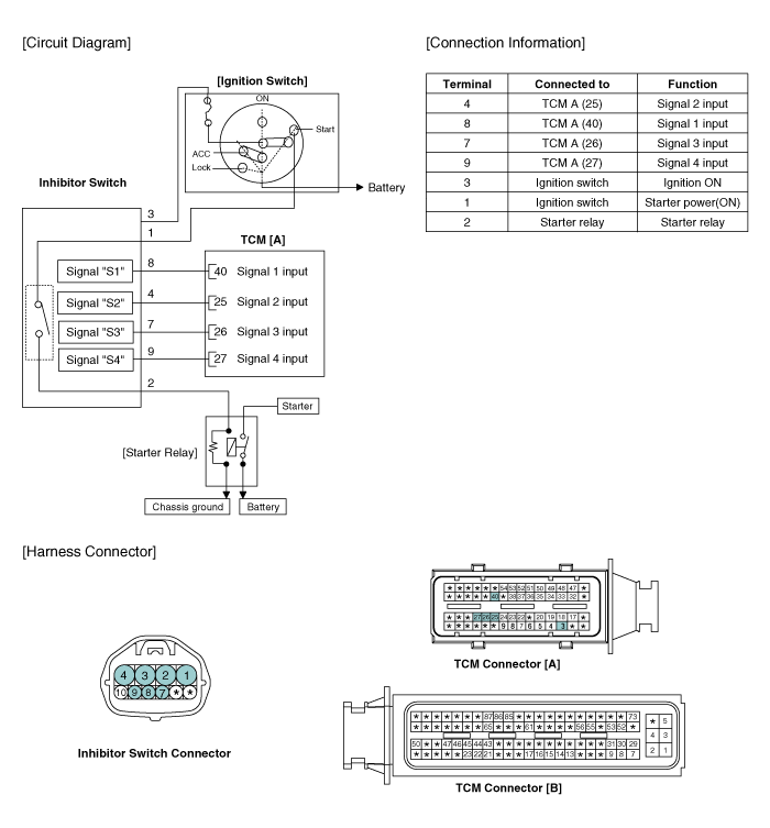
 Inhibitor Switch Specifications
Specifications Type: Combination of output signals from 4 terminals Specifications Power supply (V)12Output typeCombination of output signals Signal Code Table PIN No.PP-RRR-NNN-DDSignal "1"12V12V00000Signal ...
 Inhibitor Switch Repair procedures
Inspection • Thoroughly check connectors for looseness, poor connection, bending, corrosion, contamination, deterioration, or damage. Power Circuit Inspection 1. Disconnect the Inhibitor ...
Other information:
Kia Optima Hybrid (TF HEV) 2016-2020 Service Manual: Driver Airbag (DAB) Module and Clock Spring Components and Components Location
Components 1. Driver Airbag (DAB)2. Steering Wheel3. Clock Spring ...
Kia Optima Hybrid (TF HEV) 2016-2020 Service Manual: Active Air Flap(AAF) Repair procedures
Removal 1. Remove the front bumper. (Refer to BD group - "Front bumper") 2. Remove the headlamps. (Refer to BE group - "Headlamps") 3. Remove the air guards (A). 4. Unfasten the 2 bolts (A) and 2 fasteners (B). 5. Disconnect the AAF (Active air flap) actuator connector (A). 6. Remove the AAF (Active ...