Kia Optima Hybrid: Automatic Transaxle Control System / Engine Clutch Control Solenoid Valve (E/C_VFS) Repair procedures
| Inspection |
| 1. |
Turn ignition switch OFF. |
| 2. |
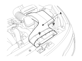
Remove the air duct (A).
|
| 3. |
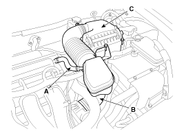
Remove the air cleaner assembly.
|
| 4. |
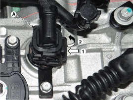
Remove the solenoid valve connector (A).
|
| 5. |
Measure resistance between signal terminal and ground terminal. |
| 6. |
Check that the resistance is within the specification. |
| Removal |
Replacing an on/off solenoid valve (SS-A, SS-B) does not
require additional hydraulic pressure adjustment; however, the hydraulic
pressure will need to be adjusted after replacing the VFS solenoid
valve. If replacing the VFS solenoid valve; also replace the valve body
assembly.
(Refer to Hydraulic System - "Valve Body") |
 Engine Clutch Control Solenoid Valve (E/C_VFS) Schematic Diagrams
Circuit Diagram ...
 26 Brake Control Solenoid Valve(26/B_VFS) Description and Operation
Description 26 brake control solenoid valve(26/B_VFS) is attached to the valve body. This variable force solenoid valve directly controls the hydraulic pressure to the 26 brake. ...
Other information:
Kia Optima Hybrid (TF HEV) 2016-2020 Service Manual: ETC (Electronic Throttle Control) System Repair procedures
Inspection Throttle Position Sensor (TPS) 1. Connect the GDS on the Data Link Connector (DLC). 2. Start the engine and measure the output voltage of TPS 1 and 2 at C.T. and W.O.T. Throttle AngleOutput Voltage (V)TPS 1TPS 2C.T0.3 ~ 0.94.2 ~ 5.0W.O.T1.5 ~ 3.03.3 ~ 3.8 3. Turn the ignition switch OFF and ...
Kia Optima Hybrid (TF HEV) 2016-2020 Service Manual: Compressor Oil Repair procedures
Oil Specification 1. The HFC-134a system requires synthetic (POE) compressor oil whereas the R-12 system requires mineral compressor oil. The two oils must never be mixed. 2. Compressor (POE) oil varies according to compressor model. Be sure to use oil specified for the model of compressor. • Since ...


