Kia Optima Hybrid: Blind Spot Detection System / Description and Operation
| Description |
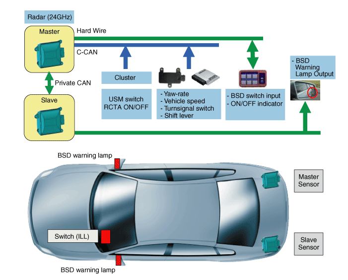
| – |
BSD (Blind Spot Detection)
Warning range is dependent on your vehicle speed. However, if
your vehicle speed is speedy about 10km/h than other vehicle, the
warning is not operated. |
| – |
LCA (Lane Change Assist)
When the vehicle is approaching to your vehicle at high speed, the warning is operated. |
| – |
RCTA (Rear Cross Traffic Alert)
When your vehicle moves backward, the sensor detects the approaching vehicles and warning is operated. |
| 1. |
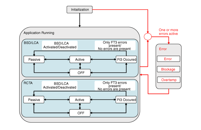
When starting the engine with the switch OFF, OFF mode is ON.
? The systems can be separately controlled based on each
activation conditions. For example, BSD & LCA system is ON by BSD
switch button and RCTA system is ON by RCTA USM switch. |
| 2. |
When pressing ON switch in OFF mode, Passive mode is ON. |
| 3. |
If starting the engine with the switch OFF, Passive mode is ON.
? When IGN is ON, the switch is in the initial state: The last position is kept.
|
| 4. |
If you start the engine with BSD switch ON or if you turn on
BSD & LCA with BSD switch off, the warning lamp of the door mirror
turned on for 3 seconds. |
| 5. |
If the activation conditions (speed and curvature radius) are met while driving, Active mode is ON(warning issued). |
| 6. |
If the activation conditions (speed or curvature radius) are not met while driving, Passive mode is ON(warning suppressed). |
| 7. |
Depending on the detected errors, BSD & LCA system (including RCTA system) becomes Fail mode. |
| 8. |
If the detected error is removed, BSD & LCA system (including RCTA system) changes to the last mode before Fail mode. |
| 9. |
If pressing OFF switch while the system is running, the system becomes OFF mode.
? Since the systems controlled separately, only BSD &
LCA system becomes OFF mode when pressing BSD switch OFF. And only RCTA
system becomes OFF mode when choosing RCTA USM OFF. |
| 1. |
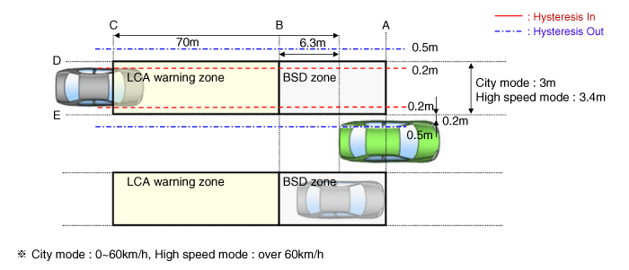
Warning zone
|
| 2. |
Conditions for BSD warning ON
 The entire body of the target vehicle is located behind the line A. The entire body of the target vehicle is located behind the line A. Any part of the target vehicle pass the line B. Any part of the target vehicle pass the line B. Any part of the target vehicle passes the line D and Hysteresis In. Any part of the target vehicle passes the line D and Hysteresis In. The entire part of the target vehicle passes the line E and Hysteresis In. The entire part of the target vehicle passes the line E and Hysteresis In.
|
| 3. |
Conditions for BSD warning OFF
 The entire body of the target vehicle moves before the line A. The entire body of the target vehicle moves before the line A. The entire body of the target vehicle moves behind the line B. The entire body of the target vehicle moves behind the line B. The entire body of the target vehicle passes the line D and Hysteresis Out. The entire body of the target vehicle passes the line D and Hysteresis Out. The entire part of the target vehicle passes the line E and Hysteresis Out. The entire part of the target vehicle passes the line E and Hysteresis Out.
|
| 4. |
Conditions for LCA warning ON
 The entire body of the target vehicle is located behind the line B. The entire body of the target vehicle is located behind the line B. Any part of the target vehicle pass the line C. Any part of the target vehicle pass the line C. Any part of the target vehicle passes the line D and Hysteresis In. Any part of the target vehicle passes the line D and Hysteresis In. The entire part of the target vehicle passes the line E and Hysteresis In. The entire part of the target vehicle passes the line E and Hysteresis In. In the all above condition, TTC(Time to Collision) is not less than 4.5 sec. In the all above condition, TTC(Time to Collision) is not less than 4.5 sec.
|
| 5. |
Conditions for LCA warning OFF
 The entire body of the target vehicle is located before the line B. The entire body of the target vehicle is located before the line B. The entire body of the target vehicle pass the line C. The entire body of the target vehicle pass the line C. The entire body of the target vehicle passes the line D and Hysteresis Out. The entire body of the target vehicle passes the line D and Hysteresis Out. The entire body of the target vehicle passes the line E and Hysteresis Out. The entire body of the target vehicle passes the line E and Hysteresis Out. In the all above condition, TTC(Time to Collision) is not more than 4.5 sec. In the all above condition, TTC(Time to Collision) is not more than 4.5 sec.
|
| 6. |
Sensor activation conditions
 BSD & LCA switch (indicated by the switch LED) is on. BSD & LCA switch (indicated by the switch LED) is on. Vehicle Speed: 30km/h or faster Vehicle Speed: 30km/h or faster Curvature radius: 100m or more Curvature radius: 100m or more Relative car speed: All except -10 ~ 250?/h Relative car speed: All except -10 ~ 250?/h("-" means overtaking the preceding vehicle) |
| 7. |
Sensor deactivation conditions
 BSD & LCA switch (indicated by the switch LED) is off. BSD & LCA switch (indicated by the switch LED) is off. Vehicle Speed: 28 km/h or slower Vehicle Speed: 28 km/h or slower Curvature radius: 70m or less Curvature radius: 70m or less Relative car speed: All except -10 ~ 250?/h Relative car speed: All except -10 ~ 250?/h("-" means overtaking the preceding vehicle) |
| 8. |
System control prohibition
 The radar is covered by debris: System conditions - Blockage message is outputted The radar is covered by debris: System conditions - Blockage message is outputted
 The radar installation is damaged by an outside shock: Send the error code The radar installation is damaged by an outside shock: Send the error code BSD & LCA system fails: Send the error code BSD & LCA system fails: Send the error code The radar is overheated: System conditions - Over Temperature message is outputted. The radar is overheated: System conditions - Over Temperature message is outputted. |
| 9. |
Rear Cross Traffic Alert (RCTA)
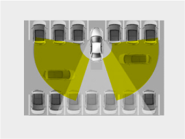
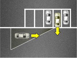
 This function helps the driver
to detect an approaching vehicle from the rear that cannot be visually
identified when the driver drives in reverse to pull the vehicle out
from a parking spot. This function helps the driver
to detect an approaching vehicle from the rear that cannot be visually
identified when the driver drives in reverse to pull the vehicle out
from a parking spot. A warning is generated for the
target vehicle if it is within two seconds based on TTC (Time to
Collision). People are not considered as approaching targets when
warning the driver. (A warning may not be generated.) A warning is generated for the
target vehicle if it is within two seconds based on TTC (Time to
Collision). People are not considered as approaching targets when
warning the driver. (A warning may not be generated.)
|
| 10. |
Rear cross traffic alert (RCTA)
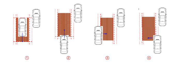
When your vehicle moves backwards from parking lot, the sensor detects the approaching vehicles and gives information driver.
Operating conditions
Warning type
|
| 11. |
Non-operating condition
|
| 12. |
Examples of Miss-Maintenance
• Check for the condition of Bumper-Skin
- If Bumper-Skin is covered with some snow or dirt, a performance of warning system is risk for degradation.
• Check for Bumper surrounding
- If metal objects are near Radar-Sensor, false-alarm can be occurred.
• Check for Bumper-shape and Condition of installation
- If Bumper and Radar-Sensor is installed incorrectly, a performance of warning system is risk for degradation.
• Check for the installation condition of Bumper, Bracket and Radar-Sensor
if Mis-Alignment is occured.
- Bumper : Installation condition, Cracks ont the bumper
- Bracket : Modification, Disconnection, Bracket positioning
- Sensor mount : Screw loosened, Check for foreign object
• Check for Switch LED
- It’s not fed into DTC because check for failure in disconnection and short-circuit is impossible. |
 Components and Components Location
Components 1. BSD unit (RH : Master/ LH : Slave)2. BSD switch3. BSD warning lamp (Built in the outside mirror) ...
 Repair procedures
Diagnosis With GDS 1. BSD system defects can be quickly diagnosed with the GDS. GDS operates actuator quickly to monitor, input/output value and self diagnosis. 2. Connect the cable of GDS to the data ...
Other information:
Kia Optima Hybrid (TF HEV) 2016-2020 Service Manual: Description and Operation
Limitations Of The Navigation system GPS Signal Reception State As the GPS satellite frequency is received/transmitted in straight lines, reception may not work if hiding devices are placed on or near the GPS antenna or when traveling through the following locations. • Tunnels • Basement parking ...
Kia Optima Hybrid (TF HEV) 2016-2020 Service Manual: Injector Repair procedures
Inspection 1. Turn the ignition switch OFF. 2. Disconnect the injector connector. 3. Measure resistance between the injector terminals 1 and 2. 4. Check that the resistance is within the specification. Specification: 13.8 ~ 15.2? [20°C(68°F)] Removal 1. Turn the ignition switch OFF and disconnect the ...

